


INTRODUCTION
The S2 alar-iliac (S2AI) screws are often used for lumbosacral fixation at the base of long spinal deformity constructs [1]. First described by Sponseller [2] and Chang et al. [3], the S2AI screw has similar biomechanical load-to-failure as traditional iliac screws [4] while allowing screws to be in-line with S1 screws. While initially described using fluoroscopy, a free-hand technique has been described and was shown to be both safe and accurate [5-7]. In severe spinal deformities, additional pelvic fixation beyond the standard 2 screws may help achieve and maintain correction, and also increase the rigidity of the construct. With a thorough understanding of pelvic anatomy, multiple pelvic screws, such as bilateral dual S2AI screws, may be placed safely to achieve stability and accommodate additional rods to perform powerful correction techniques. In this paper, we illustrate the safe placement of a 5-screw/5-rod construct across the spinopelvic junction in a complex revision case utilizing 4 S2AI screws as well as an iliac screw for a kickstand rod [8].
SURGICAL TECHNIQUE
The patient is positioned prone with careful padding in the standard fashion on an Orthopedic Systems Incorporated frame with the axillae and abdomen free. Subperiosteal exposure of the spine is performed. Decompression, facetectomies, and osteotomies are performed as necessary to achieve mobility and relieve any compression. Pedicle screws are placed in a freehand fashion.
For the S2AI screw, the surgeon should place the screw from the contralateral side. Subperiosteal dissection is performed to expose the S1 and S2 foramina. The posterior superior iliac spine (PSIS) can be palpated with the tip of the bovie and used as an additional reference for freehand screw placement [7]. The typical S2AI starting point is midway between the S1 and S2 foramina in the cephalocaudal direction, and on the lateral border of the S1 and S2 foramina in the mediolateral direction. The decision must be made before this point as to whether single or dual S2AI screws will be used. If using dual S2AI screws, the bony bridge between the 2 foramina is divided into thirds with 1 screw in the top third and the other in the bottom third. A 3.5-mm acorn-tipped burr is used to create a pilot hole. The planned screw start points should be in-line with the S1 pedicle screws. The surgeon should start with the distal screw path first, as this can achieve maximal length and establish the inferior trajectory boundary against the cortical bone of the sciatic notch. A 2-mm blunt-tipped pedicle probe is advanced towards the sacroiliac (SI) joint, at which point the hard cortex will be felt (approximately at 50-mm depth); the pedicle probe should be used with the tip facing posterior up till this point to prevent anterior perforation. A ball-tip probe confirms an intraosseous trajectory. Once past the SI joint, the tip of the pedicle probe may then be turned 180┬░ to face anteriorly, and the probe should be advanced while aiming for the anteroinferior iliac spine. The trajectory is directed approximately 40┬░ laterally in the axial plane and approximately 24┬░ caudally in the sagittal plane. While the exact angulation varies between patients, staying perpendicular to the sacral laminar slope is a useful guide when using the freehand technique. The intraosseous tunnel should again be confirmed with a ball-tip probe. A curved clamp on the ball-tip probe may be used to measure the depth of the screw needed, often 80ŌĆō90 mm. The path is then undertapped by 1ŌĆō2 mm, and the screw can be subsequently inserted using a power drill. At this time, attention may be turned towards the second more proximal S2AI screw. The same steps are taken in the preparation of the second screw path, using the first screw as a reference for trajectory and adjusting as needed based on feedback from the blunt-tipped pedicle probe.
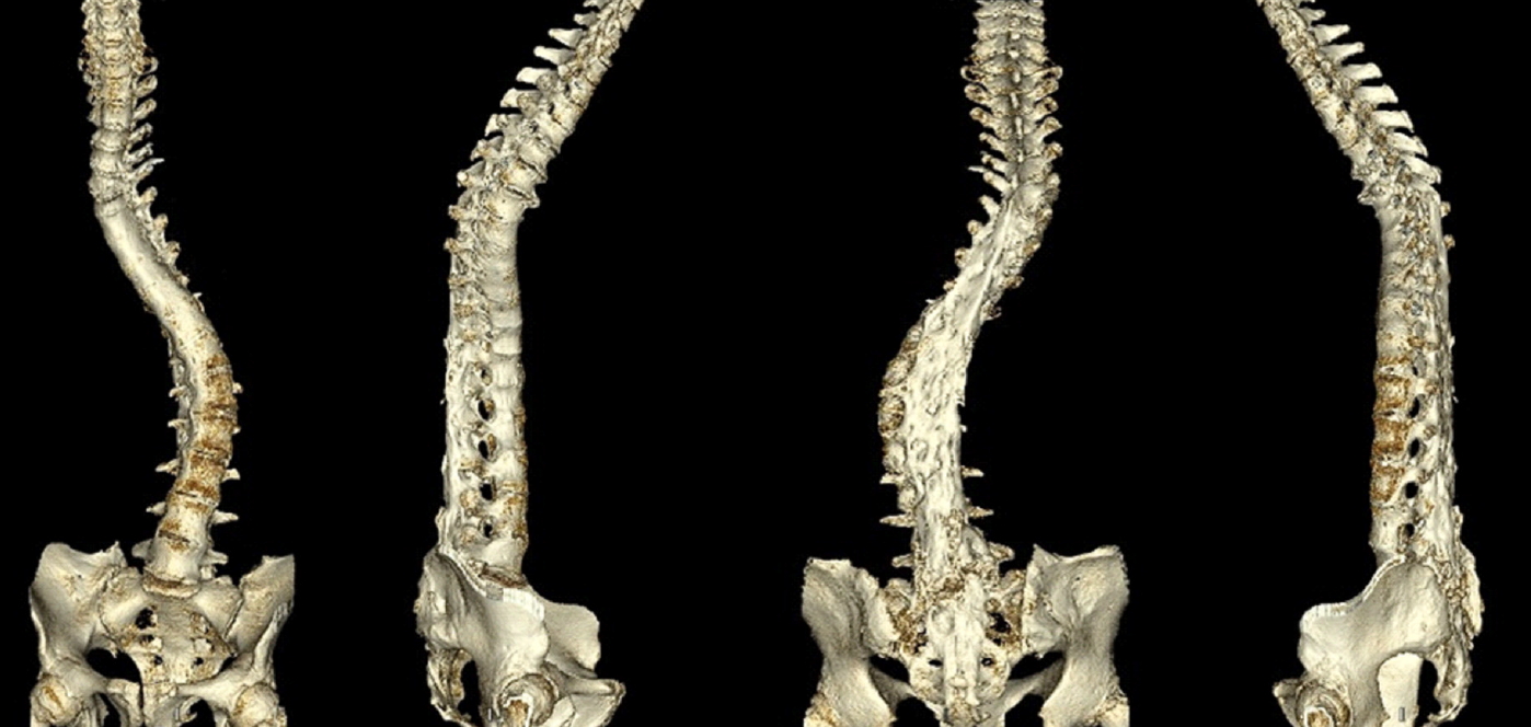
Once the overall spinal construct has been completed including rod placement, if further correction of coronal malalignment is necessary, a kickstand rod may additionally be placed in the ilium on the side of the trunk shift. Dissection is performed approximately 4ŌĆō5 cm proximal to the PSIS, until the outer table of the ilium is partially visualized. The burr is again used to establish a starting point at the superior ilium, and a long straight pedicle probe may be used to create a path straight distally, using the outer table of the ilium as a guide for the sagittal and coronal trajectory. Often a 7.5- to 8.5-mm iliac screw may be used, between 70ŌĆō80 mm in length. Often the kickstand screw does not cross the proximal S2AI screw. However, it is more likely when dual S2AI screws are used. There is sufficient bone for the screw to pass either anteriorly or posteriorly as needed, as illustrated in our case (Fig. 1); this emphasizes the importance of palpating the screw path with a ball-tip probe to confirm intraosseous trajectory while preparing the kickstand screw path.
A 5.5- or 6.0-mm kickstand rod is then placed into the iliac screw and dominoed to the main spinal construct to allow for the spinal construct to pelvis distraction and correction of rigid coronal malalignment.
CASE PRESENTATION
Patient A is a 61-year-old female with a longstanding history of scoliosis treated with Harrington rod instrumentation in 1969 with subsequent removal in 1990. She had been fused down to L5 and now presented with severe distal degeneration at L5ŌĆōS1, with fixed coronal and sagittal imbalance in the setting of a flatback syndrome (Figs. 1, 2A, and 2C). The patient complained of persistent pain mostly in her back and some in her bilateral legs extending down into her feet. She also noted numbness to her bilateral calves and feet. At this point, the patient could only tolerate standing or walking for 10 minutes at a time. On exam, the patient was pitched forward. She had a mild weakness with ankle and toe dorsiflexion on the left. Imaging showed a prior fusion from T5ŌĆōS1 (Fig. 1), with 49┬░ of residual thoracic curve, 54┬░ lumbar curve, 44┬░ of thoracic kyphosis and only 5┬░ on lumbar lordosis. She had a positive sagittal alignment of 17.4 cm, and her C7 plumb line was 7.5 cm to the right. Given the patientŌĆÖs persistent pain and severe coronal and sagittal imbalance, she was taken to the operating room (OR) for a planned revision posterior instrumentation and fusion from T3 to sacrum and ilium, L5 pedicle subtraction osteotomy (PSO), and interbody fusions at L4ŌĆō5 and L5ŌĆōS1 (Fig. 2B, D).
The patient was brought to the OR and placed prone in standard fashion. We applied Gardner-Wells tongs with 6.8 kg of traction. Her previous incision was used, and the prior fusion mass was exposed, showing a solid fusion from T7ŌĆōL5, with movement at L5ŌĆōS1 as suspected, and at T3ŌĆō7 as well. Facetectomies were performed from T3ŌĆō7, and decompressions at L4 to S1. We then placed bilateral dual S2AI screws as described above, as well as our iliac screw for the kickstand rod. Reduction screws were placed at L5 and S1, and an interbody cage was placed. We placed the remaining pedicle screws from T3ŌĆō7 and L1ŌĆō4, and an intraoperative computed tomography scan was used to confirm the acceptable placement of all screws (Fig. 3). A temporary rod was then placed on the left side 2 levels above and 1 level below L5 as well as a hook rod construct at L3 down to S2. The L5 PSO was performed. Excellent lordosis was obtained by compressing across the central hook rod construct. A permanent 5.5- to 6.0-mm hybrid rod was then placed on the right side from T3 to the S2AI screws contoured to maximize sagittal correction; of note, this rod had a domino connector placed before setting cap placement to attach to the kickstand rod. The left rod was then contoured and placed from T3 to S2 as well. After intraoperative X-ray, the right hemipelvis was noted to be high. So a 5.5-mm cobalt chrome rod was placed between the domino connector on the right and our kickstand iliac screw. The domino connector was tightened, and we sequentially distracted across this kickstand rod using a rod gripper to push the right hemipelvis down, thus obtaining even more coronal correction. After all set caps were tightened, a 4th rod was contoured and placed from the central hook rod construct to a domino connector at the T8 level, and a final 5th rod was placed on the left side from a domino above L1 down to the S1-iliac junction. Lastly, an interbody cage was placed at the L4ŌĆō5 level. A total of 5 rods crossed the lumbosacral junction, two 6.0-mm and three 5.5-mm cobalt chrome rods. The patient is now 2 years postoperative, and excellent alignment has been well maintained without complication (Fig. 2B, D).
DISCUSSION
In spinal deformity surgery, especially complex revision cases, stability across the lumbosacral junction is critical and relies greatly on the quality of pelvic fixation. Insufficient stability at this level can result in pseudarthrosis and implant failure [9-12]. Fortunately, the pelvis has enough volume and cortical mass to accommodate several large-diameter screws. We discuss and illustrate the safe and effective placement of multiple S2AI and pelvic screws to achieve rigid fixation. The use of dual S2AI screws bilaterally, in addition to a kickstand rod, has helped maintain significant correction in the patient discussed here [8]. With a solid foundation established in the pelvis, various techniques may be employed to insert additional rods across the lumbosacral junction to reinforce the overall spinal construct [13-16] for both structural support as well as achieving additional lumbar lordosis [17,18]. It has been shown that the use of multirod constructs can prevent rod failure and pseudarthrosis [12], likely by increasing mechanical stability and reducing L5ŌĆōS1 motion [15]. Four-rod constructs have been shown to be stronger in a biomechanical and cadaveric model [13,19]. We illustrate the safe use of multiple rods across the lumbosacral junction in this case, by using both a hook rod construct and domino connectors ŌĆō ultimately though these additional rods rely on the integrity of the pelvic fixation to provide their support. Through our experience, we recommend at least 3 rods across the lumbosacral junction in any adult spinal deformity case requiring pelvic fixation, and considering more than 3 rods, especially across 3-column osteotomy sites. For long spinal constructs in patients with significant adult spinal deformity, we believe the use of multiple pelvic screws to a multirod construct is a safe and effective way to provide long-term correction and clinical success, but further study is necessary to demonstrate this objectively.