Quantitative Reduction of Basilar Invagination With Atlantoaxial Dislocation by a Posterior Approach
Article information

Abstract
Objective
This study evaluated the feasibility and efficacy of quantitative reduction and fixation to treat basilar invagination (BI) with atlantoaxial dislocation (AAD).
Methods
Posterior occipitocervical angle (POCA), occiput–C2 angle (Oc–C2A), clivusaxial angle (CAA), and C2–7 angle (C2–7A) were considered for quantitative reduction. Twelve patients with BI complicated with AAD received posterior interarticular release and individualized cage implantation to restore vertical dislocation. The POCA was adjusted using cantilever technology to further reduce the horizontal dislocation and adjust lower cervical vertebral angle. All patients received a radiological follow-up for ≥12 months. Improvements in spinal cord function were evaluated using Japanese Orthopedic Association (JOA) score.
Results
All the patients received successful quantitative reduction for BI-AAD, and bony fusion was achieved without spinal cord injury after surgery for 12 months. The JOA score was improved significantly to 15.2 ± 0.9 twelve months after surgery (p < 0.01). Radiological follow-up revealed that individualized cage and POCA play vital roles in quantitative correction: (1) distance of the dens above McRae’s line and atlantodens interval were restored to normal level, respectively; (2) changes in Oc–C2 angle (ΔOc–C2A), C2–7 angle (ΔC2–7A), clivus-axial angle (ΔCAA), and POCA (ΔPOCA) were all caused by changes in axis tilt. Based on the changes of radiological parameter we deduced the formula for quantitative reduction by linear regression analysis: -ΔPOCA = ΔOc–C2A = -ΔC2–7A = ΔCAA.
Conclusion
Quantitative posterior reduction by individualized cage and adjusting ΔPOCA is feasible for treating BI with AAD.
INTRODUCTION
Basilar invagination (BI) is caused by congenital skull base and atlas dysplasia, which leads to a high odontoid protrusion into the occipital foramen. Patients often present with occipitalization of the atlas, atlantal lateral mass dysplasia, atlantoaxial articular surface sloping, and C2–3 fusion. These factors create stress concentration and atlantoaxial instability, which promote the formation of atlantoaxial dislocation (AAD) [1,2]. In patients with BI and AAD (BI-AAD), vertical and horizontal displacement of the odontoid process leads to ventral compression of the medulla oblongata, causing numbness, local pain, and sphincter dysfunction. Severe cases involve respiratory dysfunction and can be life-threatening. Thus, active treatment should be administered [3,4].
Widely used surgical treatments aim to relieve the pressure on the medulla and cervical spinal cord and maintain or reconstruct atlantoaxial stability [3,5]. In 2004, Goel [6] reported that implanting a lateral joint fusion cage achieved good results in treating BI-AAD. In our previous work, we demonstrated that quantitative correction of sagittal deformity in AAD is feasible [7]. As reported by Riel et al. [8], posterior occipitocervical angle (POCA) is a simple and valuable tool during occipitocervical fusion and may aid the design and testing of fusion implants and their application in the operating room. Another advantage of POCA measurement is that the shaping angle of titanium rod is approximately equal to postoperative POCA. However, lower cervical kyphosis may occur postoperatively due to high occiput–C2 angle (Oc–C2A), and postoperative dysphagia and dyspnea may occur due to low Oc–C2A. Preoperative planning is essential to avoid these abnormal angle related complications according to our reduction formula: -ΔPOCA =ΔOc–C2A = -ΔC2–7A=ΔCAA. Therefore, it is necessary to perform quantitative correction for BI-AAD patients. But whether quantitative correction could be achieved by customized cage and adjusting postoperative POCA is still unknown.
In this study, POCA, occiput–C2 angle (Oc–C2A), clivus-axial angle (CAA), and C2–7 angle (C2–7A) were considered for quantitative reduction. We used specific shaped titanium rod in combination with cantilever technique and customized cage to achieve individualized correction of sagittal deformity for BI-AAD patients, and performed the Japanese Orthopedic Association (JOA) score to evaluate the locomotor recovery. After the pre- and postoperative comparison, we obtained the quantitative correction formula: -ΔPOCA=ΔOc–C2A= -ΔC2–7A=ΔCAA, which confirmed that angle of cage and titanium rod angle are approximately equal to ΔOc–C2A and postoperative POCA. Therefore, it is feasible and necessary to correct the vertical dislocation by the height of cage, and restore normal Oc–C2A by adjusting fusion angle of cage and shaping angle of titanium rod (preoperative POCA–ΔPOCA).
MATERIALS AND METHODS
1. General Data
Twelve Patients with developmental BI-AAD were included in this study. A total of 12 patients were included (7 men and 5 women). Their ages ranged from 23 years to 69 years with an average age of 37.6 years. The duration of symptoms ranged from 3 months to 20 years. Limb numbness, progressive weakness of the extremities, and occipitocervical pain were the top 3 main complaints. This work was carried out in accordance with Declaration of Helsinki. This study was approved by the Institutional Review Board (IRB) of Xuanwu Hospital Capital Medical University (IRB No. Xuanwu-CZ-202169). Written informed consent was obtained from all patients included in this study.
2. Preoperative Assessment
All patients underwent preoperative dynamic lateral radiography, reconstructive computed tomography (CT), and magnetic resonance imaging (MRI) of the cervical spine. POCA is defined as the angle formed by the intersection of the line drawn tangentially to the flat posterior aspect of the occiput, between the foramen magnum and occipital protuberance, and the straight line parallel to that of the posterior margin of the C2 vertebral body. The tangential line on the occiput approximates the portion of the occiput used for fixation [8].
All the measurements of radiological parameters were listed in Table 1 and shown in Supplementary Fig. 1. JOA scores were assessed to evaluate preoperative clinical status. If the patient had C2–3 fusion, the inferior endplate line of the C3 vertebra was used instead of that of the C2 vertebra. If the patient was not in a horizontal position during the CT scan, the preoperative C2–7A (pre-C2–7A, Cobb angle between inferior endplate of C2 and C7 vertebrae) would be corrected as follows:

Measurements of radiological parameters
The corrected pre-C2–7A (pre-cC2–7A)= pre-C2–7A+presFH–0.5° [7]. (sFH, slope of Frankfort horizontal line)
3. Presurgical Planning
1) Selection of fusion cage
(1) Length of fusion cage: The fusion cage width was 8 mm, and the length was 15–18 mm. A suitable length was selected based on the articular surface length (Fig. 1).

Selection of fusion cage. (A) Customized fusion cage was selected according to the pre-ML distance, articular surface length, and the expected post-Oc–C2A. (B) Representative cage with 6 mm of height, 18 mm of length, and 5° of fusion angle. (C) Representative cage with 8 mm of height, 18 mm of length, and 5° of fusion angle. (D) Representative cage with 10 mm of height, 18 mm of length, and 5° of fusion angle. ML, McRae’s line.
(2) Height of fusion cage: There were 8 models of fusion cage: the height of the trailing edge of the fusion cages was 5–12 mm with 1 mm as the spacing. The appropriate height of fusion cage was selected based on the odontoid process length over McRae’s line (Pre-ML distance).
(3) Fusion angle: The fusion angle should be high in the front and low in the rear-10° or 0°. To restore the physiological lordosis, the appropriate fusion cage angle was selected as follows:
If pre-cC2–7 ≥ 20°, 5° fusion angle would be selected.
If pre-cC2–7 < 20°, 0° fusion angle would be selected.
2) Shaping of titanium rod angle to appropriate post-POCA
3.5-mm occipitocervical fixation rod was shaped individually to achieve appropriate post-POCA, based on pre-cC2–7A and pre-POCA (Fig. 2):

Selection of titanium rod. (A) Diagram shows that the angle of titanium rod was shaped individually to achieve appropriate post-POCA. (B) Representative rod with 91° of post-POCA. (C) Representative cage with 97° of post-POCA. (D) Representative cage with 103° of post-POCA. POCA, posterior occipitocervical angle.
If pre-cC2–7 ≥ 20°, post-POCA= pre-POCA–10°–20°
If pre-cC2–7< 20°, post-POCA= pre-POCA–0°–10°
4. Surgical Procedure
With the patient in prone position, cervical traction was only applied intraoperatively after anesthesia with weights of approximately 5–8 kg during surgery. Monitoring of the spinal cord with motor evoked potential and somatosensory evoked potential were used throughout the surgery. Using a posterior midline incision, the occiput to the C2 spinous process was surgically exposed, separated to the lateral edge of the C1–2 joint, and cut off at the C2 nerve root to expose the C1–2 articular surface (Supplementary video clip 1). Quantitative reduction techniques included the following steps (Fig. 3).

Steps in facet joint release and cage implantation in a patient with basilar invagination (BI) and atlantoaxial dislocation (AAD). (A) The joints are bilaterally distracted using a joint loosening tool, and the anterior muscles and ligaments are released. (B) The articular cartilage is widely removed using a joint facet scraper. The size of the spacer depends on the available space within the distracted joint space. (C) Customized lateral mass intervertebral fusion cages, which are tapered at one end for easier placement, are inserted in the joint space. (D) The C2 pedicle screws are placed. Use of the cantilever technique further reduces the horizontal dislocation and adjusts the Oc–C2 angle. (E) A computed tomography (CT) scan shows severe BI-AAD. (F) The intraoperative parasagittal CT image shows the joints with spacers in situ. (G) The intraoperative sagittal CT image shows that the BI and AAD are well reduced.
1) Facet joint release and cage implantation technique
The facet joint capsule between the atlas and axis was opened, and the lateral mass joint was loosely opened with a specially-designed spreader (25 mm long, 2 mm thick, 4–10 mm wide, and interval 1 mm) (Fig. 3A). After entering the joint space, the lateral mass joint was loosely opened by rotating and prizing the spreaders, and the tension band in front of the atlantoaxial vertebra was gradually released. After the joint space was expanded to a predetermined height, an articular surface scraper (25 mm long, 2 mm thick, 4–10 mm blade width, and interval 2 mm) was used for slow rotation in the joint space. Its blade was used to remove cartilage on the articular surface and to expose the bony articular surface (Fig. 3B). To avoid articular surface damage, the blade was blunt on one side and sharp on the other. Based on the preoperative plan, one fusion cage (Weigao Co., Ltd. Shandong, China) with autogenous bone graft (e.g., from iliac bone) was inserted between the bilateral joints (Fig. 3C).
2) Adjusting POCA by cantilever and occipitocervical fixation technique
Most BI patients have occipitalization of the atlas or dysplasia of the C1 posterior arch. This makes insertion of the C1 pedicle screws difficult and risky. For patients with C1 assimilation, no motion functions existed between C1 and Oc, and abnormal course of the vertebral artery and abundance of venous plexus prevented proper exposure of C1 lateral mass and screw placement. There was also a risk of hypoglossal canal injury during screw placement. Thus, patients with occipitalization of the atlas or dysplasia of the C1 posterior arch underwent occiput-to-C2 fixation with C2 pedicle screws (Figs. 2, 3D). An occipital titanium plate (Weigao Co., Ltd.) was fixed to the keel of the suboccipital cranium, and bilateral C2 pedicle screws (Weigao Co., Ltd.) were placed. If the pedicle screws of the axis could not be safely implanted, C2 and C3 lateral mass screws were used.
Fixed titanium rods were prebent to the appropriate curvature, based on the preoperative plan. Bilateral titanium rods were placed at the tail end of the cervical vertebral screw. The cantilever technique was used to further reposition the odontoid process. After O-arm scanning showed satisfactory reduction with appropriate POCA, the screw joints were locked (Fig. 3F–G). Based on the amount of spinal cord compression, C1 posterior arch resection or foramen magnum decompression was performed in some patients. Wounds were washed, and incisions were sutured. Patients could move out of bed wearing a neck bracket, which was used for 3 months.
5. Postoperative Assessment and Follow-up
Patients were observed prospectively for ≥ 12 months. Twelve months postoperatively, JOA scores were assessed to evaluate the clinical status. Every patient was evaluated by the same operator. All patients underwent dynamic CT and MRI. The postoperative corrected C2–7A (post-cC2–7A) was determined based on sFH and the change between pre- and postoperative T1S (the slope of T1) [7]:
post-cC2–7A=post-C2–7A–(pre-T1S–post-T1S)+(post-sFH–0.5)
6. Statistical Analysis
IBM SPSS Statistics ver. 22.0 (IBM Co., Armonk, NY, USA) was used for statistical analysis. R2>0.8 were considered as cut-off values for a good linear fitting equation. Paired t-test was used for comparing mean values between the 2 groups. Data are presented as means±standard deviation. p<0.05 was considered statistically significant.
RESULTS
1. Intraoperative Findings
The joints were dissected open in all 12 patients. No injury of vertebral artery occurred. Three patients had abnormal vertebral arteries that crossed the C1–2 joint posteriorly, these arteries were gently dissected away from the soft tissue before placing the fusion cages. All 12 patients had occipitalization of the atlas and underwent occipital–C2 fixation. Two of the patients had an axis high-riding vertebral artery that prevented placement of the C2 pedicle screws. Therefore, C2 and C3 lateral mass screws were used. The mean duration of surgery was 123 minutes (range, 95–151 minutes), and mean blood loss was 90 mL (range, 65–120 mL). Representative case reports can be seen in Figs. 4 and 5.

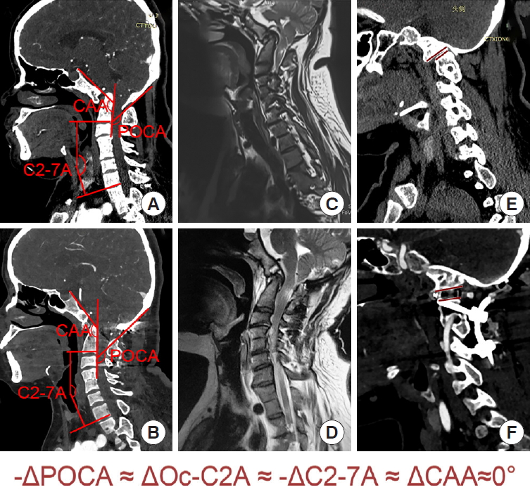
Case demonstration of the quantitative reduction. A 42-year-old man presented with progressive quadriparesis. Before the operation, his pre-Oc–C2 angle was 2.5°, corrected C2–7 (pre-cC2–C7) angle was 45°, pre-POCA was 140°, and pre-CAA was 138.4°. We used a cage with a height of 6 mm and an angle of 10°. The postoperative findings were as follows: post-Oc–C2 angle was 18.9°, postoperative corrected C2–7 (post-cC2–7) angle was 29.8°, post-POCA was 126°, and post-CAA was 152.9°. (A) Preoperative computed tomography (CT) sagittal reconstruction of the cervical spine shows severe BI-AAD, fusion of the C1 arch with the occiput, and increased cervical lordosis. (B) The postoperative CT image shows anatomical reduction and a corrected cervical lordosis. (C) Preoperative magnetic resonance imaging (MRI) shows compression at the cervicomedullary junction. (D) Postoperative MRI shows complete decompression. (E) Preoperative parasagittal CT images show facet orientation. (F) The postoperative parasagittal image shows the joints with the spacer in situ. C2–7, cervical vertebrae 2–7; CAA, clivusaxial angle; Oc, occiput; POCA, posterior occipitocervical angle. ΔC2–7A, difference in the pre- and postoperative C2–7 angle (C2–7A); ΔCAA, difference in the pre- and postoperative clivus-axial angle; ΔOc–C2A, difference in the pre- and postoperative Oc–C2 angle; ΔPOCA, difference in the preand postoperative posterior occipitocervical angle; AAD, atlantoaxial dislocation; BI, basilar invagination.
Case demonstration of the quantitative reduction. A 47-year-old woman presented with limb numbness and progressive quadriparesis. Before the operation, her pre-Oc–C2 angle was 5.3°, preoperative corrected C2–7 (pre-cC2–7) angle was 9.1°, pre-POCA was 135.4°, and pre-CAA was 135.8°. We used a cage with a height of 6 mm and angle of 0°. After surgery, her post-Oc–C2 angle was 6.1°, postoperative corrected C2–7 (post-cC2–7) angle was 8.6°, post-POCA was 133.8°, and post-CAA was 136.3°. (A) Preoperative computed tomography (CT) sagittal reconstruction of the cervical spine shows severe BI-AAD, fusion of the C1 arch with the occiput, and a normal cervical lordosis. (B) Postoperative CT shows anatomical reduction and an unchanged cervical lordosis. (C) Preoperative magnetic resonance imaging (MRI) shows compression at the cervicomedullary junction. (D) Postoperative MRI shows complete decompression. (E) Preoperative parasagittal CT images show facet orientation. (F) The postoperative parasagittal image shows the joints with the spacer in situ. C2–7, cervical vertebrae 2–7; CAA, clivus-axial angle; Oc, occiput; POCA, posterior occipitocervical angle. ΔC2–7A, difference in the pre- and postoperative C2–7 angle (C2–7A); ΔCAA, difference in the pre- and postoperative clivus-axial angle; ΔOc–C2A, difference in the pre- and postoperative Oc–C2 angle; ΔPOCA, difference in the pre- and postoperative posterior occipitocervical angle; AAD, atlantoaxial dislocation; BI, basilar invagination).
2. Radiological Follow-up
All the patient achieved good decompression and solid fusion with bone bridge formation after surgery for 12–18 months. The mean postoperative distance of the dens above ML was significantly shorter than the mean preoperative distance (-1.04± 1.01 mm vs. 4.71± 2.09 mm, p< 0.05). Atlantodental interval was restored to normal level (< 3 mm) in all patients.
3. Correlations Between Angle Changes
Geometric measurements (Table 2) revealed that changes in the Oc–C2A, C2–7A, CAA, and POCA were caused by changes in the axis tilt (Fig. 6). The Chamberlain line was fixed relative to the clivus plane and the line drawn tangentially to the flat posterior aspect of the occiput between the foramen magnum and occipital protuberance. This was the same for lines tangential to the posterior surface of the odontoid process and the inferior endplate of the axis. In addition, the sFH was fixed in order to keep the head looking forward horizontally and ensure deformities at the craniovertebral junction had little impact on T1S.

Pre- and postoperative radiologic measurements

Geometric measurements and linear regression. (A) Geometric measurements show that the changes in the Oc–C2 angle (Oc–C2A), C2–7 angle (C2–7A), CAA, and POCA are all caused by the changes in the axis tilt. Linear regression analysis reveals (B) a significant negative correlation between ΔOc–C2A and ΔC2–7A (ΔC2–7A = -0.91718 ×ΔOc–C2A; R2= 0.9001) and (C) a significant negative correlation between ΔPOCA and ΔOc–C2A (ΔOc–C2A = -0.85014 ×ΔPOCA; R2= 0.9247). (D) A significant negative correlation also exists between ΔPOCA and ΔCAA (ΔCAA = -0.85280 ×ΔPOCA; R2= 0.9219). C2–7, cervical vertebrae 2–7; CAA, clivus-axial angle; Oc, occiput; POCA, posterior occipitocervical angle. ΔC2–7A, difference in the pre- and postoperative C2–7A; ΔCAA, difference in the pre- and postoperative clivus-axial angle; ΔOc–C2A, difference in the pre- and postoperative Oc–C2A; ΔPOCA, difference in the pre- and postoperative posterior occipitocervical angle. Green area in part B indicated the angle changes pre- and postoperation.
Linear regression analysis revealed a significant negative correlation between ΔPOCA and ΔOc-C2A, and a significant negative correlation between ΔPOCA and ΔCAA (Fig. 6):
ΔOc–C2A= -0.85014×ΔPOCA (R2=0.9247)
ΔCAA= -0.85280×ΔPOCA (R2= 0.9219)
A significant negative correlation also existed between dOc–C2A and dC2–7A (Fig. 6):
ΔC2–7A= -0.91718×ΔOc–C2A (R2= 0.9001)
Compared with preoperative measurements, ΔOc–C2A, ΔPOCA, ΔCAA, ΔC2–C7A were 8.87°± 6.45°, -8.975°± 7.33°, -9.80°±6.21°, and 8.88°±6.49°, respectively. Therefore, the quantitative reduction formula was proposed as follows:
-ΔPOCA=ΔOc–C2A= -ΔC2–7A=ΔCAA.
4. Clinical Improvements
Eleven of the 12 patients (91.7%) improved clinically. One patient (8.33%) had stable symptoms. The postoperative follow-up period was 12–18 months. At the 12th month after surgery, the mean postoperative JOA score was significantly improved to 15.2 ± 0.9 compared with the preoperative score of 12.2 (p< 0.05). No complications occurred intra- or postoperatively.
DISCUSSION
1. The Pathogenesis of BI-AAD
The pathogenesis of BI-AAD is associated with the formation of platybasia, occipitalization of the atlas, atlantoaxial dysplasia, atlantoaxial joint tilt, and Kleip-Feil malformation, among others [9]. In 2004, Goel [6] classified BI as type A (BI-AAD) and type B (BI occurs without AAD). Height loss in the C1 lateral mass causes the C2 odontoid to be placed far caudally, thereby forming BI. If the atlantoaxial cruciate ligament and lateral articular surface develop normally, the odontoid maintains a normal anatomical relationship without dislocation. This type of simple BI is type B, and it is often combined with a reduced cranial fossa volume, Chiari malformation, and syringomyelia, among others. If the upper joint of the axis is tilted downward, the lateral joint is unstable, and occipital ossification of the atlas and the congenital fusion of C2–3 result in more concentrated stress on the odontoid. As the weight of the head is sustained over time, the odontoid is dislocated to a posterior superior position, thereby forming typical BI combined with AAD, which is type A.
2. Direct Posterior Reduction and Fusion
For the past 3 decades, the conventional treatment strategy for BI-AAD was transoral excision of the odontoid process followed by posterior instrumented fixation [4]. In treating BI-AAD, the focus has shifted from transoral decompression with posterior fusion to direct posterior reduction and fusion [10]. On this basis, we customized cages of different sizes, heights, and angles, based on preoperative CT measurements, and we restored the vertical dislocation through posterior intra-articular cage implantation. At the same time, the POCA was adjusted using the cantilever technique to reposition the horizontal dislocation and adjust the angle of the lower cervical spine. Occipitocervical internal fixation was then conducted, which obtained a good therapeutic effect because the reduction effect was improved, and the lower cervical curvature was found to be within a normal range.
3. Customized Cage Implantation and Facet Joint Release
Based on the pathogenesis of BI, the most reasonable strategy for reducing BI is to supplement the height of the atlantoaxial lateral mass that was lost because of atlanto-occipital fusion between the occipital condyle and articular process of the axis. The lost height of the lateral mass of atlas can be effectively compensated for by implanting a cage of a certain height between the atlantoaxial vertebrae, and thereby achieve an anatomical reduction of the BI. AAD in BI is usually irreducible.
Two important obstacles in reducing AAD in BI are the anterior atlantoaxial tension band (i.e., alar odontoid ligament, apical ligament, musculus longus capitis, and musculus longus colli) and the lateral articular process deformity noose. The deformed lateral joint and anterior atlantoaxial tension band need to be released before the fusion cage is implanted between the occipital condyle and the lateral mass of the axis. Wang et al. [11] reported transoral transection of the anterior atlantoaxial tension band. This technique releases the atlantoaxial articular process; however, additional anterior surgery increases the incidence of surgical trauma and related complications. Salunke et al. [12] and Chandra et al. [13] reported an arthroplasty procedure for deformed atlantoaxial facets to release the strangulation of the joints. This technique is ineffective in releasing the anterior atlantoaxial tension band. In addition, destroying the osseous articular surface of the atlantoaxial joint will increase the possibility of fusion cage collapse and vertebral artery injuries. Therefore, based on the morphological data of lateral atlantoaxial joints in patients with BI, we designed special joint-space release tools and interarticular fusion cages.
After a narrow joint spreader is inserted into the articular space of the atlantoaxial vertebra and rotated, the tension band in front of the atlantoaxial vertebra can be released. This technology is key in posterior reduction of BI-AAD. The integrity of the bony articular surface of the superior and inferior articular surface must be ensured during joint-space opening. The selection and implantation of a suitable interarticular fusion cage are also very important. Placing the cage in the joint space can act as a fulcrum in an operation using the cantilever manipulation technique, correct the atlantoaxial kyphosis deformity, and reposition the atlantoaxial horizontal dislocation. At the same time, the angle of the fusion cage is closer to the osseous joint surface, which can increase the fusion rate.
4. Cantilever and Occipitocervical Fixation Technique
After implanting the interarticular cage, most of the horizontal dislocation is reduced because of the “folding chair effect.” By using the anterior cage as a fulcrum, the cantilever technique was used to further restore the horizontal dislocation and adjust the occipitocervical angle. Appropriate selection of the occipitocervical angle is very important. An improper occipitocervical angle after occipitocervical fusion may lead to short-term and long-term complications. In this study, we used accurate measurements obtained before surgery to guide intraoperative rod-shaping and to quantitatively regulate the occipitocervical angle during occipitocervical fusion. In a previous study, we had found that correction of the CAA will influence subaxial cervical lordosis (ΔCAA= -ΔC2–7A) in AAD patients [7]. Geometric measurements revealed that the changes in the 4 angles—Oc–C2A, C2–7A, CAA, and POCA—were caused by a change in the inclination angle of the axis. Linear regression analysis revealed a significant correlation between ΔPOCA and ΔOc–C2A, ΔPOCA, and ΔCAA, and ΔOc–C2A and ΔC2–7A. This equation can serve as a quantitative reference for preoperative planning. Therefore, we selected a cage with a proper angle and further adjusted the POCA through shaping the titanium rods, and we adjusted the 3 angles (i.e., Oc–C2A, C2–7A, and CAA) through a linear relationship so that the 3 angles were in a reasonable range, thereby facilitating an accurate reduction.
5. Adjustment of ΔPOCA
The POCA was used to adjust the occipitocervical angle and as the basis for shaping the titanium rod. In 2010, Riel et al. [8] named the POCA the angle between the tangent of the cortex of the occipital process and the posterior edge of the C3 and C4 articular processes on lateral x-ray of the cervical spine. They found that the POCA was between 101° and 119° in 80% of individuals. It is difficult to directly draw the connecting line between the posterior edge of C3 and C4 articular process on median CT in the sagittal position. Therefore, we introduced the line parallel to that of the posterior margin of the C2 vertebral body as an alternative line.
During occipital-cervical fixation, the screw-rod system in the occipital region is attached to the surface of the occipital cortex, and the tangent line of the cortex between the occipital protuberance and foramen magnum is nearly parallel. Additionally, the screw insertion point is placed in the region of the articular process. The connecting rod, through the cervical screw, is nearly parallel to the articular process. This method is helpful in guiding the selection of the prebending angle of the titanium rods in occipitocervical fusion [14]. Based on the formula -ΔPOCA =ΔOc–C2A = -ΔC2–7A =ΔCAA, we adjusted the POCA through shaping the titanium rods, and adjusted the 3 angles (i.e., Oc–C2A, C2–7A, and CAA) through a linkage relationship so they were within a reasonable range, thereby facilitating accurate reduction.
6. Clinical Significance of ΔOc–C2A and ΔC2–7A
The Oc–C2A and the C2–7A were each evaluated as described previously [12,15]. The average Oc–C2A in normal adults is approximately 22.4°, and the average C2–7A is approximately 9.9° [16,17]. Passias et al. [18] suggested a negative correlation between Oc–C2A and C2–7A. An excessive Oc–C2A can lead to a lower cervical kyphosis. Matsunaga et al. [19] retrospectively analyzed the clinical data of 38 patients with occipitocervical instability due to arthritis deformans. The patients underwent occipitocervical fusion surgery. All patients with an Oc–C2A > 30° had a lower cervical kyphosis. An excessively small Oc–C2A was closely associated with postoperative dysphagia and expiratory dyspnea [20]. Ota et al. [21] found a significant correlation between the change in the O–C2 angle and the change in the narrowest oropharyngeal airway space (nPAS). In the neutral position, when the occipitocervical angle decreases by 10°, the nPAS decreases by 37%.
In this group of patients, the mean± standard deviation preoperative Oc–C2A and C2–7A was 4.66°± 9.47° and 19.93°± 13.96°, respectively. These values differed from normal values [16-19]. The Oc–C2 angle was significantly lower than normal, and the C2–7A increased as the Oc–C2A decreased. We corrected the vertical dislocation by the height of cage, and restore normal Oc–C2A by adjusting fusion angle of cage and shaping angle of titanium rod (preoperative POCA–ΔPOCA). Therefore, adjusting Oc–C2A is as effective as adjusting C1–2 facet inclination. With a pre-cC2–7 ≥ 20°, we applied a 10° fusion cage, and with a pre-cC2–7 < 20°, we applied a 0° fusion cage. The postoperative Oc–C2A should be greater than or equal to the preoperative angle. At the same time, we attempted to correct the C2–7A to be within a normal range and avoid a lower cervical kyphosis.
7. Clinical Significance of ΔCAA
The CAA was first described by Vangilder and Menezes [22]. It was suggested that an angle < 150° may cause medullary compression. A positive correlation exists between the CAA and the cervicomedullary angle in patients with an upper cervical deformity before and after surgical reduction [23]. The CAA is a good index for judging the reduction of the upper cervical spine during surgery and for evaluating decompression of the spinal cord postoperatively.
The ΔC2–7A was negatively correlated with the ΔCAA. We attempted to correct the CAA as close to 150° as possible, whilst simultaneously maintaining the postoperative C2 cervicomedullary angle 7A within normal limits. During the final follow-up, the CAA of the 12 patients increased by 8.9° on average. The average value of the CAA correction after surgery was 149.79°, and some patients still had a less-than-normal CAA. This may be because patients with BI often have a flat skull base, a larger basal angle, a higher clivus inclination, and a smaller CAA. If the CAA in these patients is reset to normal, a lower cervical lordosis will inevitably occur. In patients with a less-than-normal CAA, ventral compression was relieved based on MRI, and their clinical symptoms improved.
CONCLUSION
Quantitative posterior reduction by customized cage and individualized ΔPOCA is an feasible method for treating BI-AAD.
Notes
The authors have nothing to disclose.
Acknowledgements
This work was supported by Beijing Municipal Natural Science Foundation, (Beijing Municipal Administration of Hospital Grant, PX2017002), Beijing Municipal Administration of Hospitals (Beijing Natural Science Foundation Grant, 7172091), Beijing Municipal Health Commission (Beijing Health Commission Independent Innovation Fund 2018-2-2014), and Beijing Science and Technology Plan (Z191100006619048).
SUPPLEMENTARY MATERIALS
Supplementary Fig. 1 and video clip 1 can be found via https://doi.org/10.14245/ns.2040496.248 and https://doi.org/10.14245/ns.2040496.248.v1, respectively
Radiographic measurement of the Oc–C2 angle (Oc–C2A), C2–7 angle (C2–7A), CAA, and the POCA on sagittal plane. The Oc–C2A is the angle between Chamberlain’s line and the line tangential to the inferior aspect of the axis. The C2–7 Cobb angle is the angle between inferior endplate of C2 and C7 vertebrae. The CAA is the angle between the clivus plane and the straight line parallel to that of the posterior margin of the C2 vertebral body. The POCA is the angle formed by the intersection of a line drawn tangential to the flat posterior aspect of the occiput between the foramen magnum and occipital protuberance and the straight line parallel to that of the posterior margin of the C2 vertebral body. C2–7, cervical vertebrae 2–7; CAA, clivus-axial angle; Oc, occiput; POCA, posterior occipitocervical angle. FH, Frankfort horizontal line; ADI, atlantodental interval; CL, cervical lordosis.
Surgical procedure of quantitative reduction of basilar invagination with atlantoaxial dislocation by a posterior approach.