The Hybrid Open Muscle-Sparing Approach in Adult Spinal Deformity Patients Undergoing Lower Thoracic Fusion to the Pelvis
Article information

Abstract
Proximal junctional kyphosis (PJK) is a difficult complication to manage following adult spinal deformity surgery. Particularly in spinal fusions from the lower thoracic spine down to pelvis, PJK is a major consideration. While the open posterior approach allows for excellent visualization and preparation of bony surfaces for fusion, disruption of posterior soft tissue structures increases risk of PJK postoperatively. Minimally invasive approaches, on the other hand, preserve posterior ligamentous structures and musculature at the proximal fusion levels however prevent the access afforded by an open approach. We describe here the hybrid open muscle-sparing approach—a technique that allows for decortication of bony surfaces as well as clear exposure of anatomic landmarks for freehand pedicle screw placement, while protecting the posterior soft tissue structures to reduce risk of PJK.
INTRODUCTION
Spinal deformity is an increasingly common problem in the adult population causing pain and disability, affecting 65% of patients over age 59 [1,2]. As older patients often have pathology at multiple levels throughout the lumbar spine, surgeons frequently must plan for a thoracolumbar decompression and fusion often including the sacrum/pelvis. While there are multiple approaches and techniques that can be employed to address degenerative scoliosis, one of the major complications associated with any fusion procedure is the development of proximal junctional kyphosis (PJK) [3,4]. PJK is defined as a sagittal Cobb angle of > 10° from the caudal endplate of the upper instrumented vertebra (UIV) to the cephalad endplate of UIV+2 proximally, or a change > 10° in the sagittal Cobb angle between UIV and UIV+2 from pre- to postoperatively [5].
In order to avoid the apex of thoracic kyphosis, proximal level selection becomes a critical step in preoperative planning for posterior decompression and fusion procedures. As a result, surgeons frequently debate whether to end the fusion construct at a lower thoracic (LT) level such as T9–12 or whether the fusion should be extended to an upper thoracic (UT) levels of T2–4. While LT fusions allow for shorter procedures, less estimated blood loss, and may have lower rates of pseudarthrosis, UT fusions allow for correction of thoracic deformity and, more importantly, have lower rates of PJK [6-8]. Radiographic PJK has been reported as high as 33% in patients with a UIV at T9 or T10 [8,9]. As such, patients without significant thoracic deformity would clearly benefit from a shorter fusion construct to the LT spine, however, this requires particular attention during surgery to mitigate the risk for development of PJK postoperatively. The major intraoperative risk factors for PJK include violation of the posterior ligamentous complex, proximal facet joint disruption, and amount of sagittal correction obtained [10-17].
Various techniques have been described to preserve the posterior ligamentous structures and respect the proximal soft tissue in these LT fusions to the pelvis. For example, percutaneous screw placement at the proximal UIV and UIV-1 levels, use of navigation, and robotic assistance have been suggested techniques to aid in preserving the posterior ligamentous structures and minimize soft tissue disruption. While these techniques do protect posterior structures, they sacrifice surgical access and bony preparation that is obtained from a fully open technique. Additionally, percutaneous screws require fluoroscopy and robotic assistance necessitates a computed tomography (CT) scan, which are eliminated in the open technique by allowing freehand screw placement. We describe here the hybrid open muscle-sparing approach (HOMSA), a less traumatic technique that allows not only for preservation of the midline posterior soft tissue complex and paraspinal musculature but also the benefits of a traditional open technique by providing access for freehand screw and rod placement, facetectomies, decortication, and graft placement at the proximal fusion construct.
SURGICAL TECHNIQUE
The patient is positioned prone with all prominences well-padded, then prepped and draped in standard fashion for any spinal deformity case. The wide draping from shoulders to the sacrum (regardless of fusion levels) will allow the surgeon maximal visual reference for alignment intraoperatively, including shoulder balance and pelvic obliquity. A midline incision can be marked from the estimated LT level to the sacrum. Palpable anatomic landmarks such as the iliac crests, ribs, and spinous processes should be marked to help the surgeon estimate incision length – correlating these landmarks with preoperative radiographs. Following incision, a standard subperiosteal exposure is performed over the mid and distal lumbar spine exposing all necessary anatomic landmarks out to the transverse processes. Proximally, the UIV and UIV-1 and UIV-2 should not be exposed; the paraspinal musculature and posterior ligamentous complex should be preserved (Fig. 1). This entails dissection to the level of the thoracodorsal fascia only. Prior to radiographic level confirmation, being conservative with the proximal dissection is advised as to not violate the posterior soft tissues. Distally, large curettes may be used at this time to thoroughly clear the exposed lumbar levels of any soft tissue and confirm visualization of the transverse processes and sacral ala bilaterally.
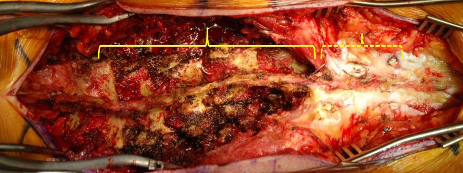
The hybrid open muscle-sparing approach. Wide exposure is completed in the distal lumbar levels to sacrum (solid bracket) – the paraspinal musculature and posterior ligamentous complex at the proximal 2–3 levels (dotted bracket) at the thoracolumbar junction are maintained.
Following adequate exposure of levels distal to the UIV-1, inferior facetectomies may then be performed at the exposed levels. Depending on the patient’s pathology, decompression and posterior column osteotomies may be performed as necessary. Following adequate decompression, instrumentation is then placed starting distally with pelvic fixation; S2-alar-iliac (S2AI) screws are preferred at our institution. Using the freehand technique and the exposed pars and transverse processes as landmarks, freehand pedicle screws are then placed starting from distal to proximal. Once screws are placed, interbody fusion(s) may be performed as needed. Once instrumentation is complete at the exposed levels, attention may then be turned to the UIV, UIV-1, and UIV-2 levels.
The skin is retracted superficially exposing the paraspinal multifidus, longissimus, and investing fascia proximally. The overlying fascia is incised over the facet approximately 2 cm from the midline in order to expose the underlying muscle fibers (Fig. 2). The avascular intermuscular plane between the multifidus and longissimus should be identified and bluntly dissected using a finger or a curved clamp (Fig. 3). Blunt dissection is critical at the UIV in order to avoid inadvertent damage to the cephalad facet capsule. The dorsal aspect of the transverse process should be palpated deep to the paraspinal musculature using a finger (Fig. 3). Once the plane is developed several centimeters a blunt cerebellar retractor may be placed between the multifidus and longissimus. The transverse process, pars, and facet joint should be visualized from the ipsilateral side in order to allow for freehand screw placement (Fig. 3). This plane may be developed at each individual proximal level being addressed cephalad to the UIV. Of note, the interspinalis muscles medially along the sinous proccesses are completely preserved.

Development of intermuscular plane. (A) The facet joint is palpated through the muscle and a small incision (dashed black line) through the fascia is made 2 cm from midline (solid black line) over the facet. (B) The avascular intermuscular plane between the multifidus (solid arrow) and longissimus (dotted arrow) is developed bluntly using a curved clamp. (C) The underlying facet and transverse process are palpated using a finger.

Exposure of anatomic landmarks. A cerebellar retractor can be placed in the intermuscular plane and used to visualize the facet joint (solid arrow), pars (dotted arrow), and transverse process laterally.
At this time at the UIV-2 level, the facet capsule may be taken down using bovie cautery and decorticated with a high-speed burr. Decortication of the visualized transverse process should likewise be performed at this time before access is limited by screw placement. The pedicle screw may then be placed - depending on the depth of the muscle, a reduction screw may be used to aid in rod positioning and set cap placement (Fig. 4). Following UIV-2 and UIV-1 screw placement, the screw at the UIV may be similarly placed using the freehand technique. Particular care should be taken to limit proximal exposure and maintain the facet joint cephalad to the UIV; the facet joint between the UIV and UIV+1 should be not visualized. At the UIV, screws are placed through anatomic reference of the pars interarticularis, the transverse process, and the valley formed between the lamina and transverse process. This is critical especially at the T7–9 level, as the starting point is more cephalad and closer to the facet joint. The surgeon should be vigilant when determining the cephalad/caudad trajectory, as the contralateral bony anatomy cannot be visualized.

Instrumentation through the hybrid open muscle-sparing approach. The pedicle screw can then be placed using the freehand technique and exposed anatomic landmarks using a pedicle probe (A) and tap (B), followed by the pedicle screw (C).
At this time, the contoured rod is seated. Given the limited dissection proximally, the rod is first seated submuscularly in the UIV and UIV-1 screw heads. The rod may need to be rotated initially 180° in order to engage the proximal screws submuscularly and then can be rotated back down for the distal screws (Fig. 5). The distal end can then be maneuvered into the S2AI screw and the intermediate reduction tulips may be adjusted to engage the rod once seated proximally and distally. Additional deformity correction can then be performed using compression/distraction, coronal bending, and in situ rod bending. Lastly, additional rods across the lumbosacral junction are placed extending submuscularly to the UIV-1 level as needed. At this time, decortication is performed and autograft and/or allograft is placed over the exposed transverse processes caudally – retractors may be placed again in the intermuscular plane and graft may be placed over the previously decorticated area between the UIV and UIV-2.

Rod placement from proximal to distal. (A) The rod is contoured and can be rotated 180° to be placed proximally first submuscularly. (B) Once seated, the rod may be rotated 180° down into the distal screws, and autograft and allograft may be placed once correction is obtained.
CASE REVIEW
Patient TV is a 57-year-old female presenting with adult idiopathic scoliosis first recognized at age 40, stating her curve was approximately 30° at the time. Over the past 3–4 years, she reported progressive low back pain that recently started causing radiating leg pain down to her feet bilaterally, worsening while standing. On presentation, her pain was equally distributed in her back and legs and denied any lower extremity numbness or weakness. Physical therapy, anti-inflammatories, transcutaneous electrical nerve stimulation treatment, and epidural steroid injections provided minimal relief. The patient had a normal dynamic and static neurologic exam of her lower extremities with full strength throughout.
Preoperative imaging (Fig. 6) revealed a main thoracic curve of 53° and a 70° thoracolumbar curve with a 34° fractional lumbosacral curve. The patient was shifted coronally 1.5 cm to the left. Sagittal imaging showed the patient had lumbar hypolordosis of 31°, a pelvic incidence of 51°, and a positive sagittal vertical axis of 2 cm. A CT myelogram showed multilevel stenosis from L2 down to S1. After extensive discussion with the patient, a T10-sacrum/pelvis posterior spinal decompression and instrumented fusion was planned in order to relieve her significantly debilitating back and leg pain.

A 57-year-old female presenting with adult idiopathic scoliosis. (A, E) The patient presented with a 53° main thoracic, 70° thoracolumbar, and 34 fractional lumbosacral curve. The patient had a trunk shift with coronal imbalance 1.5 cm to the left. (C, G) The patient presented with lumbar hypolordosis of 31°, pelvic incidence of 51°, and kyphosis through the thoracolumbar junction resulting in a positive sagittal vertical axis of 2 cm preoperatively. (B, D, F, H) Postoperative imaging following a posterior spinal instrumentation and fusion from T10 to the pelvis with transforaminal Lumbar Interbody Fusion at L4–5 and L5–S1 using the hybrid open muscle-sparing approach technique.
The patient was brought to the operating room and placed prone in the standard fashion – the neck maintained in a neutral position using Gardner-Wells tong traction. A midline incision was made anticipating a T10-pelvis fusion and subperiosteal dissection was used from L1 to the sacrum. Following soft tissue debridement, inferior facetectomies were performed from T12–L1 to L5–S1 and the upper lumbar spine was then packed as attention was turned to the L5–S1 level.
At L5–S1, a posterior column osteotomy (PCO) through the ligamentum flavum, inferior spinous process of L5, and the superior facectomies of S1 was performed. Bilateral foraminal decompression was also performed and the osteotomy was widened on the left side to expose the annulus of L5–S1. Similarly, at L4–5, a PCO was performed with bilateral foraminal decompression and the decompression was widened on the right side to expose the annulus of L4–5. PCOs and decompression were subsequently performed at L3–4, L2–3, and L1–2.
Once decompression was complete from L1–S1, instrumentation was then placed starting distally. S2AI screws were placed using freehand technique bilaterally, dual-headed screws placed at S1 bilaterally, and reduction pedicle screws were placed at L5 and L4. A temporary rod was then used at L5–S1 to place an interbody implant and graft from the left side, followed by L4–5 on the right side. Once the interbody implants were in position, the remaining screws from L3 to T11 were placed using freehand technique. At the T10–12 levels, a HOMSA technique was used and the pars, facets, and transverse processes were exposed at T10 and T11. Inferior facetectomies and decortication of the transverse processes were performed, followed by freehand placement of reduction pedicle screws through the intermuscular window.
A 5.5-6.0 cobalt chrome plus rod was then contoured and placed first on the right side, passed loosely into the tulip heads of the T12 and T10 screw submuscularly. The rod was captured distally to the S2AI, S1, L5, and L4 screws, bypassing the right-sided screws of the thoracolumbar concavity. Next, compression across L5 into S1 and L4 into L5 on the right side was done to address the fractional lumbosacral curve by horizontalizing L4 and L5 while simultaneously creating L4–S1 lumbar lordosis. The left-sided rod was then placed, again loosely engaging the proximal T10 and T11 screws submuscularly then capturing the S2AI screw up to L3. Distraction across the lumbosacral fractional curve on the left rod then allows for additional correction in the coronal plane while lordosis is maintained by the locked right rod. The remaining reduction screw heads and set caps were placed to complete the correction from L4 proximally on the left side. A third rod was then placed on the right side to capture the medial head of the S1 screw, as well as the bypassed screws at T11–L3, including the medial head of the dual-headed T12 screw. An additional rod was then passed from the medial head of the left S1 rod to a domino connector between L1 and L2. The remaining transverse processes and bony surfaces distally were decorticated, and autograft and allograft were placed; the HOMSA plane was again utilized to place graft around the construct underneath the paraspinal muscles at T10 and T11. A standard layered spinal closure was completed and there were no intraoperative neuromonitoring changes or complications throughout the case.
In conclusion, when performing a LT fusion to the sacrum/pelvis, surgeons must pay particular attention proximally to mitigate the risk of developing postoperative PJK. The HOMSA is a novel method that utilizes the avascular intermuscular plane in the paraspinal muscles to visualize key anatomic landmarks with minimal dissection, which not only allows for freehand screw placement and decreased fluoroscopic exposure for both the patient and surgical team, but also allows for facetectomies with thorough decortication of the transverse processes similar to the open technique. This access provides for less proximal soft tissue and muscle dissection without sacrificing the visualization of an open technique. We believe the HOMSA is an excellent surgical option to decrease the risk of PJK while optimizing LT fusions to the pelvis for adult spinal deformity patients.
Notes
The authors have nothing to disclose.