Simultaneous Robotic Single Position Oblique Lumbar Interbody Fusion With Bilateral Sacropelvic Fixation in Lateral Decubitus
Article information

Abstract
Single position lateral fusion reduces the need for a secondary surgery and robotic guidance allows for potentially higher accuracy of screw placement. We expand the role of robotics with a simultaneous workflow where 2 surgeons can work in single position surgery and discuss the technical feasibility of placement of S2-alar-iliac (S2AI) screws in the lateral position. A 70-year-old male presented with chronic back pain and bilateral leg pain with the left side worse than the right. He subsequently underwent an L3–S1 oblique lumbar interbody fusion (OLIF) with a minimally invasive L3-ilium robotic posterior spinal fixation simultaneously in single lateral position with S2AI screws. The software planning requisite of robotics allowed for a preoperative plan where lumbar cortical screws were used to line up with bilateral S2AI screws. Intraoperatively, the OLIF was performed anterior to the patient which allowed for a second surgeon to perform the posterior stage of screw placement simultaneously in overlapping fashion during OLIF exposure. Once all screws were placed, the OLIF discectomy and cage placement were completed. As the OLIF incision is closed, rodding proceeds posteriorly with subsequent closure simultaneously as well. Operative time from skin incision to skin closure was 3 hours and 47 minutes. We present here a novel technical report on the recommended workflow of simultaneous robotic single position surgery OLIF and demonstrate the feasibility of placement of sacroiliac fixation in the lateral decubitus position. We believe this technique to be minimally invasive, effective, with the benefit of shortening valuable operating room case time.
BACKGROUND AND IMPORTANCE
The oblique lumber interbody fusion (OLIF) approach, which allows access to the spine via a small corridor between the psoas muscle and the aorta, was introduced by Mayer in the late 1970s as an alternate to the anterior lumbar interbody fusion [1]. Indications include amelioration of degenerative diseases of the spine in L1–S1, as well as coronal and sagittal alignment correction [2]. Studies have shown a decreased risk of psoas muscle and lumbar plexus injury, higher rates of vertebral body fusion and thorough disc clearance, and quicker mobilization after surgery compared to newer techniques such as the extreme lateral indirect fusion [3-5]. Risks of the OLIF procedure include iliac vessel injury, transient neurological damage, and sympathetic chain injury [3].
Recently, Huntsman et al. [6] reported successful pedicle screw placement with navigated robot-assisted single position lateral lumbar interbody fusion. There is a paucity of studies of robot-assisted single position OLIF procedures, and none yet describing either a 2-surgeon simultaneous approach or the technical feasibility of robotic-assisted placement of S2-alar-iliac (S2AI) screws. We report a novel 2-surgeon simultaneous robotic single position surgery (SR-SPS) OLIF with bilateral sacropelvic fusion in lateral decubitus.
CLINICAL PRESENTATION
1. Patient Presentation
A 70-year-old male presented with chronic back pain and bilateral leg pain with the left side worse than the right. Informed consent was obtained from the patient. Having failed conservative management of physical therapy, trigger point injections, and epidural steroid injections, he sought surgical care. His preoperative Oswestry Disability Index (ODI) was a 48/100. Magnetic resonance imaging demonstrated degenerative change with disc height collapse causing bilateral neuroforaminal stenosis at L3–4, L4–5, and L5–S1 (Fig. 1). Due to his equal distribution of back pain and leg pain, he was offered an L3–S1 OLIF with a minimally invasive L3-ilium robotic posterior spinal fixation simultaneously in single lateral position with S2AI screws (Mazor X Stealth Edition, Medtronic Sofamor Danek, Memphis, TN, USA). Sacropelvic fixation was chosen to reduce the risk of postoperative sacroiliac joint pain after multilevel stabilization and fusion in light of the patient’s body mass index of 38.4 kg/m2 [7].

(A) Sagittal T2-weighted magnetic resonance imaging showing collapse of disc spaces and degenerative change from L3–S1 with axial section of L3–4 (B), axial section of L4–5 (C), and axial section of L5–S1 (D).
2. Software Planning
The Mazor X planning software is used to prepare the targets and trajectories of the patient’s construct design based on a thin-cut preoperative computed tomography (CT). Because the L3-ilium construct is planned as a minimally invasive design, cortical screw trajectories are planned which allow for better rod line-up (Fig. 2) [8]. In addition, the L3–4, L4–5, and L5–S1 disc spaces can be targeted so that the robotic arm can be used for intraoperative guidance for direction down to the respective disc spaces while minimizing intraoperative fluoroscopy. Additionally, the predictive software alignment can simulate a variety of cage footprints for surgeon clinical decision making (Fig. 3).
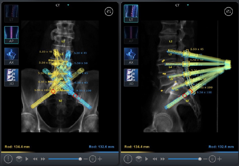
Mazor X software robotic plan showing planned screw trajectories from L3 to S2AI, as well as the marked disc space levels from L3–4 to L5–S1. Note that the cortical lumbar screws line up well with the S2AI screws for a straight planar rod design.
Mazor X software robotic plan with simulated view of oblique interbody cage placement from L3–4 to L5–S1 and anticipated “ideal” correction.
3. Operative Technique
The patient is positioned in right lateral decubitus with the left side facing up (Fig. 4). The back is positioned as close to the edge of the table as possible to allow for reach of the posterior pedicle screw and iliac screw instruments. Because the surgical technique allows both surgeons to work near simultaneously, there are various stages where it is advised that the posterior (pedicle screw) surgeon or anterior (OLIF) surgeon pause and wait to maximize robotic accuracy and guidance. These steps are outlined below.

Lateral decubitus positioning of the patient with the back positioned as close to the posterior edge as possible, and the abdomen allowed to fall away to the bed without anterior bolsters to allow freedom for the oblique trajectory
1) Registration
The robotics platform is rigidly attached to the bed and to the patient’s spine via the posterior superior iliac spine. Two fluoroscopic images are then taken to align the patient’s in situ positional anatomy to the segmented preoperative CT anatomy. Once registration has occurred, great care is taken to minimize motion to the patient so as not to introduce error into the registration. This includes avoiding leaning against the patient, avoiding any heavy-handed maneuvers, and minimizing somatosensory evoked potentials signals if neuromonitoring is being used.
2) Posterior surgeon
Once the robotics platform is attached and registered, the robotic arm is first sent to the anterior surgeon’s disc space trajectories so that incisions can be planned. The arm is then sent back to the posterior screws. Due to the long segment nature of this construct, we performed a single midline skin incision for cosmesis and performed all screws transfascially. Screws were placed in the following sequence: right-sided L3, L4, L5, S1; left-sided L3, L4, L5, S1; right-sided S2AI; left-sided S2AI. Screw placement proceeds proximal to distal to maximize accuracy of the screws furthest away from the robotics platform which may have the higher risk of error. The right-side is performed first because any incisional bleeding will drain downwards, and performing the right-side last may be hindered by blood draining down from the left side. S2AI screws are both performed last because the amount of force and torque required for placement exceeds that of regular pedicle screws, which again may increase risk of mismatch error. Because of the preplanning design of the S2AI screws as well as the rigid guidance of the robotic arm, placement of the S2AI screws bilaterally is not a technically laborious task. Robotic technique for placement of screws using the Mazor X Stealth Edition platform includes the robotic knife which is inserted down to the bone, followed by the navigated dilator and cannula. Subsequently, the navigated drill, tap, and pedicle screw are placed down the robotic arm with real-time navigation on-screen to confirm an appropriate trajectory as compared to the preoperative plan. As a technical note, we use continuous power for our instruments to avoid the “start-stop” movement of hand drivers. Also, drills, taps, and screws are started just slightly above the bone before being driven down the bony path to avoid skive error.
Once all screws are placed, the posterior surgeon pauses while the anterior surgeon performs the discectomy and cage placement at all the appropriate levels. Once this is finished, the posterior surgeon can resume placement of the rods and set screws using standard minimally invasive technique. Although the surgical view of a “forest of towers” may initially be daunting, the preoperative planning has already taken into account the alignment of the screws for the rods, and rod placement is done with minimal difficulty (Fig. 5). Closure then proceeds in usual fashion.
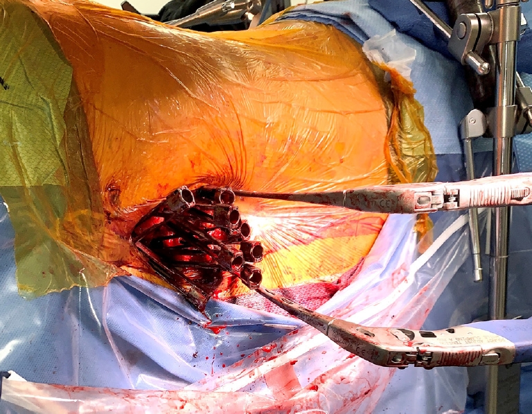
Posterior view with all screws placed causing a “forest of towers” in the surgical field. Also shown is placement of bilateral rods using minimally invasive technique and inserters.
3) Anterior surgeon
The robotic arm is sent to all disc spaces that had been preplanned on the software. This is then marked on the skin as a guide for the surgical corridor. Because the OLIF is performed under direct visualization of the disc space, skin incisions are marked anterior to the level of the disc and the iliac crest can be avoided for all levels. The robotic arm is then sent back to the posterior surgeon for placement of screws, and the anterior surgeon can proceed simultaneously with exposure down to the disc space at all levels (Fig. 6). Great care is taken not to shift or move the patient during this time to avoid introducing mismatch error in robotic guidance posteriorly. The L5–S1 disc space is exposed first via an oblique corridor, and then subsequently to save time, the L4–5 and L3–4 disc space corridors can be dilated and exposed if the posterior surgeon is still working (Fig. 7).
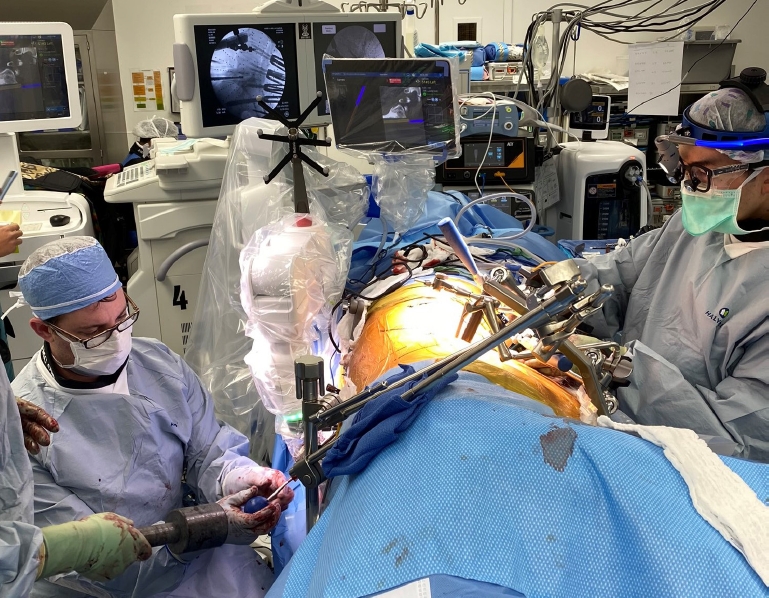
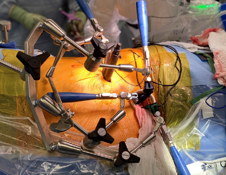
Operating room view showing both the posterior surgeon (right) and anterior surgeon (left) simultaneously overlapping in their workflow.
Anterior view showing the L5–S1 surgical corridor with 3 minimally invasive retractor blades, and the L3–4 surgical corridor with the L3–4 minimally invasive dilators. The anterior surgeon is paused now awaiting complete placement of all posterior screws.
The anterior surgeon must then pause until all the posterior screws have been placed. Once screw placement has finished, the anterior surgeon then proceeds with the OLIF discectomy and cage placement at all levels with fluoroscopic guidance. When all cages have been placed, anterior closure then proceeds simultaneously as the posterior surgeon begins the final rodding (Fig. 8).
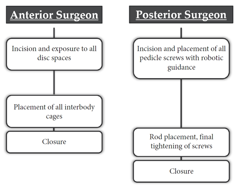
Workflow diagram of anterior and posterior surgeon.
4. Clinical Outcome
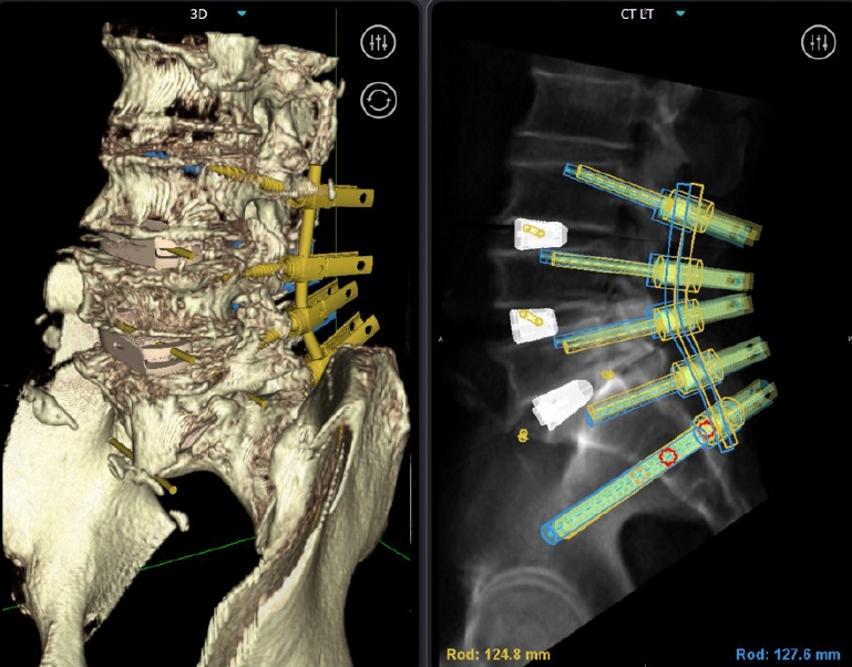
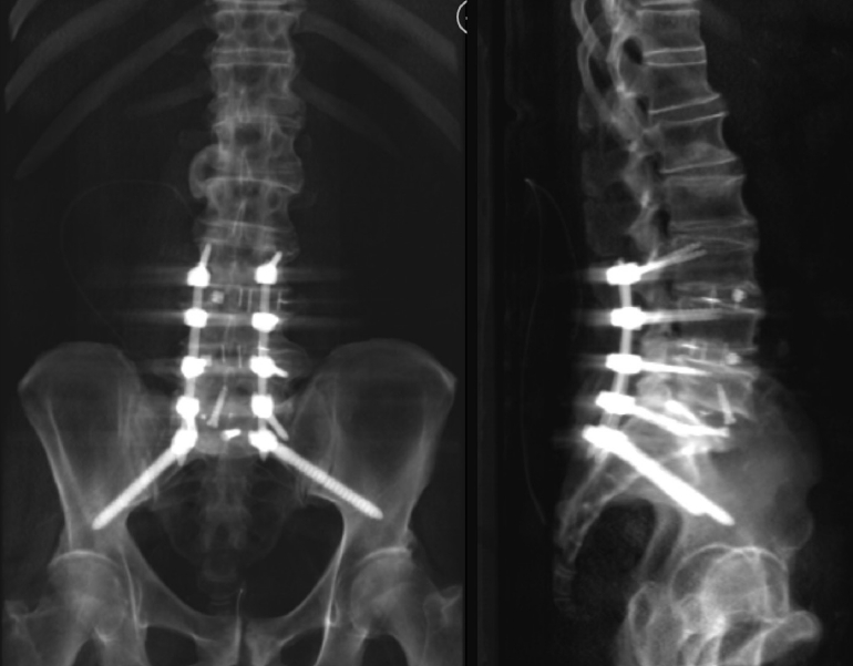
Due to the simultaneous exposure and overlapping workflow, total operative time from skin incision to skin closure for placement of 8 lumbosacral screws, 2 S2AI screws, and 3 interbody cages including L5–S1 was 3 hours and 47 minutes. Blood loss was estimated to be 100 mL. Postoperative imaging demonstrated implants to all be in good position (Figs. 9, 10). He was discharged on the third postoperative day. At 8-month follow-up, he has complete resolution of his leg pain and significant improvement in his axial back pain. There have been improvements in his visual analogue scale and ODI scores with decreases of 6 points and decreased by 34 points respectively.
Postoperative computed tomogarphy-constructs showing anteriorposterior and lateral view of the final L3-ilium construct.

Postoperative imaging showing anteriorposterior and lateral x-rays of the construct.
DISCUSSION
Single position lateral fusions reduce the need for a secondary surgery, and robotic guidance allows for potentially higher accuracy of screw placement. Additionally, completing the procedure in a single position reduces OR time, redraping, and cost of surgery [9]. We demonstrate here this technical case to build upon the role of robotics in expanding a simultaneous workflow which allows for single position surgery to be performed in an overlapping manner, as well as the technical feasibility of placement of S2AI screws now in lateral position as well.
Preoperative planning is required for all robotics platforms, which allows for input of the desired targets and trajectories which make up the patient’s construct design. The preoperative planning itself is key to the success of the construct design, as screws can be lined up beforehand to minimize frustration and difficulty in passage of the rod down to the S2AI screws. Similar to PACS (picture archiving and communication system) systems and other software programs, there is some up-front learning required for appropriate use. However, the learning curve is similarly not steep and a quick familiarity can be obtained due to intuitive directions and controls.
The benefits of performing SR-SPS are unique to both robotics and OLIF. Because the OLIF is performed anterior to the patient, this allows for the opportunity to perform the posterior stage of screw placement simultaneously in overlapping fashion to maximize efficiency and reduce both anesthesia and operating room time. Because of the accuracy and rigidity of robotic guidance, placement of S2AI screws becomes no more difficult a task than the planning design and placement of any other pedicle screw. For surgeons who are comfortable with OLIF, this technique demonstrates the feasibility of not only placement of pedicle screw instrumentation in the single lateral position, but also that extension down to the ilium is not an impediment or reason to flip to prone. This workflow provides an opportunity for tremendous efficiency and time savings while still providing the surgical goals. Although we describe here the feasibility of placement of sacroiliac fixation in the lateral decubitus position, this technical description also offers a recommended workflow for SR-SPS OLIF in general.
Over the past few years, robotic assistance in spinal surgery has also grown. Benefits of robotic aid include increased accuracy of screw placement and decreased radiation exposure. A systematic review article noted that of the 22 studies evaluating the accuracy of spinal instrumentation with robotic assistance, only one resulted in lowered accuracy in screw placement using a robot [10,11]. The literature supports the benefits of robotic assistance in reducing radiation exposure and time under fluoroscopy. Kantelhardt et al. [12] concluded that average x-ray exposure per screw was significantly lower in robotic aided surgery (34s vs 77s) in comparison to conventional methods; Lieberman et al. [13] reported lower fluoroscopy time per screw as well.
Recent studies have outlined the possibility of keeping the patient in a single position for spinal fusion surgeries. While keeping the patient in a single position, Huntsman reported a 98% success rate of pedicle screw placement with the lateral lumbar interbody fusion approach. The study also noted that there were no screw revisions needed, hence supporting the procedure’s efficacy [6]. Lamartina introduced the feasibility of conducting the extreme lateral interbody fusion with posterior fixation in the prone position [14]. This study outlined a reduced mean surgical time of 133.8 ± 26.6 minutes in the prone position, as compared to 182.8 ± 47.9 minutes in standard lateral decubitus. Walker et al. [15] report a similar lengthened mean surgical time of 203.6 ± 64.8 minutes in standard lateral decubitus, as well as similar rates of known complications [14].
CONCLUSION
We present here a novel technical report on the recommended workflow of SR-SPS OLIF and demonstrate the feasibility of placement of sacroiliac fixation in the lateral decubitus position. We believe that we have stated the advantages in terms of time savings and efficiency. The use of robotic guidance in bilateral iliac fixation in the single lateral position would significantly reduce operative and anesthesia times, without the need to flip patients.
Notes
Dr. Pham reports consultant fees with Medtronic. Dr. DiazAguilar reports no financial disclosures. Dr. Lehman reports consultant fees with Medtronic; speaking and/or teaching arrangements with Medtronic, DePuy, Stryker; grants from the Department of Defense, Defense Medical Research Development Program. Other authors have nothing to disclose.