Mechanically Relevant Anatomy of the Axis Vertebra and Its Relation to Hangman’s Fracture: An Illustrated Essay
Article information

Abstract
To describe the biomechanically relevant anatomy of the Axis vertebra and the load transfer patterns within the bone, and on that basis, to postulate its mechanism of injury, a literature review was conducted of the anatomy and biomechanics of Axis fractures. Two hypotheses have been presented: the internal gear hypothesis and the leaf spring hypothesis. Both are based on the trabecular anatomy of the vertebra and its load transmission patterns. The relationship of the Axis with Hangman’s injury is also discussed. According to the leaf spring hypothesis, the C2 pedicle corresponds to the shackle in the assembly and constitutes the weak link. The trabecular architecture of the Axis is such that the primary compression of the trabeculae is directed from the superior facet to the C2–3 endplate, with few trabeculae directed to the inferior facet. Along with the trabecular void in this area, this renders the isthmus vulnerable to trauma. The isthmus of the Axis is biomechanically susceptible to injury due to its unique anatomy in relation to the whole cervical spine and the internal load transmission patterns of the bone. The author suggests that in the flexion type of Hangman’s injury, the C1–2 posterior ligaments are disrupted and need to be addressed.
INTRODUCTION
The human C2 vertebra, also called the “Epistropheus” has been extensively studied with reference to the anatomical variation from a typical cervical vertebra, its embryology, as well as comparative anatomy in various animals, both quadruped as well as bipedal. The Axis is a unique bone in terms of its anatomy, development and location at the cranio-cervical junction [1-3]. Our understanding of its structure and function has advanced considerably though some biomechanical concepts need to be redefined to better appreciate the injury patterns of this bone and their therapeutic significance.
C2 fractures are approximately 26.8% of all cervical spine injuries. Neural arch fractures (Hangman’s injuries) account for almost 36.9% of these [4]. What makes this specific region susceptible to injury? Anatomical features, mechanical susceptibility, embryological attributes etc. have been attributed for this increased predilection. The objective of this study is to demonstrate that anatomical features like facet orientation, trabecular orientation and material voids may contribute to the structural weakness of the region and predispose to fractures. The author introduces 2 biomechanical concepts that might explain the bones’ predilection for injuries and the unique fracture patterns that arise. Additionally, the author also describes his hypothesis for the flexion and extension types of Hangman’s injuries of the Axis.
ANATOMICAL FEATURES
1. Facet Orientation
The superior articular facet of the C2 vertebra is more or less horizontally oriented in the sagittal plane and inclined downward and laterally in the coronal plane (Fig. 1A, B). In the axial plane they face antero-medially. The inferior facet (C2–3) is directed antero-inferiorly in the sagittal plane, infero-laterally in the coronal plane and more or less straight in the axial plane. The inferior facet is parallel to the rest of the subaxial cervical spine; in other words, collinear to the rest of the cervical facets. While several authors have described the morphometry of the Axis and its facet orientation, most have missed out measurements of the angular orientation of the facets in the sagittal, coronal and axial planes and the gross difference between the superior and inferior facet alignment [5-8]. Singla et al. [9] have established that the superior facets are inclined by a mean of 69.3° in the coronal plane and the inferior facets by 42.1° in the sagittal plane. There is scant information on the missing values of the facet orientation along the other Cartesian co-ordinates [10,11]. Moreover, little emphasis if any at all, has been laid on the clinical and mechanical import of this information (more attention has been paid to the feasibility of screw trajectory within the bone) [12-19].
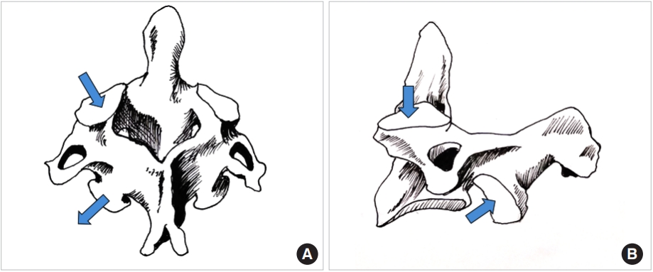
(A) Line diagram of the Axis vertebra; please note the sagittal and axial alignment of the superior and inferior facets depicted with arrows. (B) Line drawing of the sagittal view of the Axis; the sagittal plane alignment of the superior and inferior facets is pointed out by the arrows. Also note that unlike the subaxial cervical spine, the facets are not in a line.
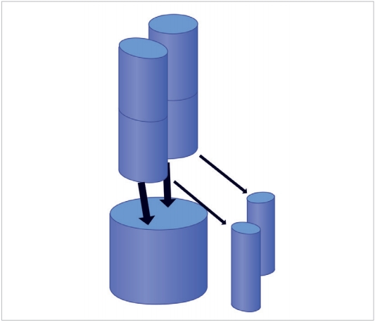
Also noteworthy is the fact that the upper facets of the C1 vertebra measure 21 mm in length and 10.36 mm in width [20] which progressively diminish to 11.6-mm length and 9.6-mm width when it reaches the inferior facet of C2 [21]. Assuming that the facets are designed to share axial loads, it may be inferred that the transmitted loads diminish in magnitude (besides the change in direction) as they travel from the cranio-cervical junction to the C3 vertebra. Represented diagrammatically in Fig. 2, it is evident that the head is supported by a 2-column structure at the C1 vertebral level which becomes a 3-column structure at the C3, where much of the load transmission is through the vertebral bodies rather than the facets. This redistribution of loads can only take place within the C2 vertebra as demonstrated by Menon and Raniga [22] (Fig. 3).
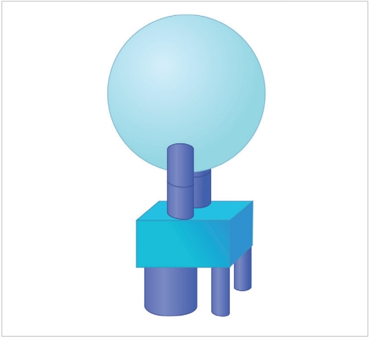
Figurative representation of the head being supported by the cranio-cervical junction. The bicolumnar support is converted to a tricolumnar support as the loads exit the Axis, represented by the square block. The anterior column is the vertebral body bearing the brunt of the load and the posterior pillars are the facet columns.
2. Trabecular Orientation
Mechano-transduction is currently accepted as a behavioral property of bone tissue, in particular cancellous bone [23]. Trabecular bone, though an anisotropic structure, has been shown to organize itself along load bearing axes to optimize load transfer [24]. Wolff’s law propounds that the trabecular orientation is a demonstration of the load bearing patterns within the bone [25]. Thus by studying the alignment of bony trabeculae one can determine the internal loads transmitted by each bone. The authors have demonstrated on volume rendered CT images that the trabecular orientation of the Axis is primarily from the superior facet to the C2–3 disc space while trabeculae running into the inferior facet are sparse [22] (Figs. 4, 5). By Wolff’s law, trabecular density and direction are surrogate measures of the of load transmitted [26,27]. This data might be interpreted as relatively little force being transmitted from the superior to inferior facet in the C2 bone. Heggeness and Doherty [28] have also reported trabecular architecture studies of the Axis but failed to emphasize the implications of this observation. The role of the facet joint orientation in the cervical spine and their contribution to mechanical load bearing has been previously reported [29,30]. Additionally, the present authors have demonstrated a consistent void within the bone in the pars interarticularis – pedicle area [22]. The void is a naturally weak area of the bone lacking the reinforcing trabecular fibers that resist bending and twisting strains; moreover, the void in the material also acts as a local stress riser predisposing to mechanical failure in this region (Fig. 6).
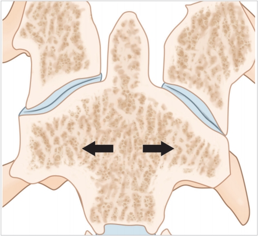
Coronal computed tomography section illustrating the trabecular anatomy of the Axis. Please note the primary compression trabeculae run down from the superior facet to the inferior end plate of the vertebral body (arrows).
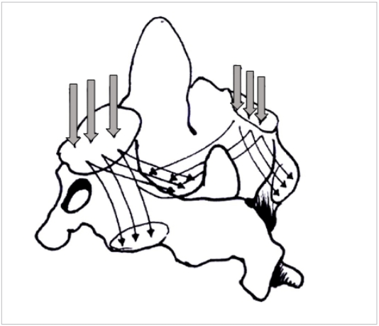
Three-dimensional figure of the C2 vertebra depicting the primary compression and secondary compression trabeculae (thin arrows; thick arrows represents the axial loads on the superior facets).

Sagittal reformatted computed tomography of the Axis illustrating the consistent void in the isthmus of the bone (arrow).
BIOMECHANICAL CONCEPTS
1. The Leaf-Spring Hypothesis
The entire cervical spine may be considered to function much alike an automobile leaf-spring. The spring in this instance is aligned vertically and loaded at the upper end by the weight of the head. Axial loads typically decrease and increase the radius of curvature of the leaves. Just as in car springs where the ends are fixed to the chasis by a shackle the lower end of the cervical spine is firmly fixed to the relatively immobile thoracic spine. The cervical spine may be imagined to comprise of 2 leaves, the vertebral bodies with the intervening discs forming the longer anterior leaf from the dens to the C7 and the posterolateral pillars comprising of the facetal masses from C3 to C7 (Fig. 7A, B). The isthmus of each vertebra connects the anterior and posterior leaves very much like the rebound clips of the car’s leaf spring. The upper end of the posterior leaf is fixed to the cranio-cervical junction by the shackle which according to the authors model is the pars interarticularis of the C2 vertebra. The bi columnar load transmission at the O–C junction gets converted to a tricolumnar loading at the C2–3 level and this is the point where the shackle comes into play. A significant change in the load direction is visualized at this region making it vulnerable to cantilever bending moments. In a car leaf spring the weakest link is this shackle where typically all mechanical failures occur and it is easy to envisage why a similar failure model exists in the C2 pars interarticularis as well (Fig. 8).
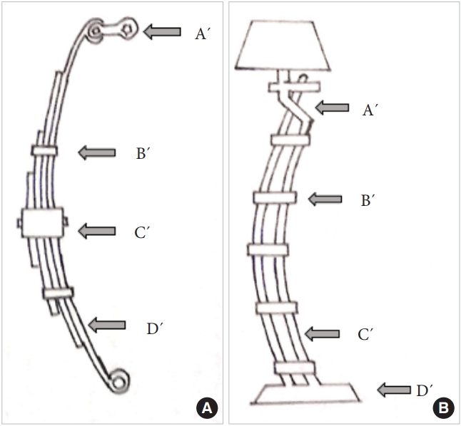
(A) The vertically oriented leaf spring of a car illustrating its salient components: A´ is the shackle. B´ represents the rebound clips and C´ represents the center bolt. D´ is the spring leaf itself. (B) The clinical depiction of the leaf spring model in the upper cervical spine. The isthmus of the C2 represents the shackle, the pedicles of the vertebrae the rebound clips (B´), and the 3 columns the 3 leaves of the spring system-C´. D´ is the base comprising of the rigid thoracic spine.
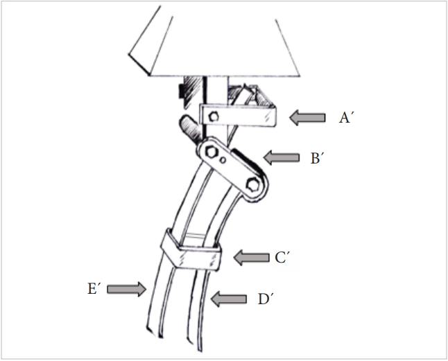
Three-dimensional model of the cervico-thoracic junction as represented by the leaf spring hypothesis. A´ is the Atlas, B´ is the isthmus of the Axis (the shackle of the spring system), C´ is the rebound clips, and D´ & E´ are the spring leaves represented by the load bearing columns of the cervical spine.
2. The Internal Gear hypothesis
The authors have propounded that the bicolumnar load transmission at the C1–2 level transforms into a tricolumnar load bearing pattern at the C2–3 level. This implies that the load magnitude and directions change within the body of the C2 vertebra-converting it into a virtual gearbox like mechanism. Just as in mechanical systems the gear is the weak link in a load transmission system and often fails in the first instance. The C2 body being a densely trabeculated structure tends to fail less often than the poorly trabeculated neural arch. Amling’s study has also emphasized the microarchitecture of the Axis vertebra as being responsible for certain injury patterns therein [31]. Additionally, the authors have demonstrated that isthmic area has consistent voids with little if any trabecular bone mass; this renders it more vulnerable to injury.
Evidently, these models are simplistic representations and do not consider the significant ligament and muscular contributions to the load sharing and distribution mechanism that exits in the living state. These soft tissue structures function as tension bands and help redistribute the axial loads imposed on the spinal column. Nevertheless, it is a 3-dimensional depiction of the force transmission as it occurs in the native state of the upper cervical spine.
DISCUSSION
The role of the Axis as a pivot for transverse plane rotation has been well established. Offiah and Day [32] have written an excellent review of the embryology and biomechanics of the cranio-vertebral junction. According to these authors the C2 is the true junctional tissue since it develops from the first and second cervical sclerotomes thus arising from the 3 adjacent sclerotomes that eventually form the C–V junction. They also describe the C0–C1 movement as being determined by the bony contours of the joints and the C1–2 joint by the ligamentous structures. Tan et al. [33] in their study on the morphometry of the Axis, have shown that the superior facets are generally oval and the inferior ones circular. The typical cervical spine anatomy of columnar articular pillars that vertically transmit loads is not followed in the C1–2 region due to the staggered arrangement of the facet joints in this area. Jaumard et al. [29] have described the normal sagittal plane angulation of the subaxial cervical facets as 20°–78° and the axial plane angle as 70°–96°. Pal et al. [30] proposed the 3-column mechanistic structure of spine where the discovertebral elements from the major anterior column and the facet bearing pillars the 2 posterior columns. By computational models these authors proposed that 23% of the axial load is transmitted by the facet joints in the cervical spine. Others have also reported that the posterior joints add significant torsional and shear resistance to the cervical spine [33,34]. Goel, Kumaresan, and others have studied finite element models and predicted that the facets carry between 38% and 48% of the loads in the mid cervical region [35,36].
CLINICAL RELEVANCE TO HANGMAN’S INJURIES OF THE CERVICAL SPINE
Korres [4] has reported Hangman’s fracture as 37% of all cervical spine injuries – the second most common fracture in this region. These authors describe hyperextension-compression as the primary mechanism of injury with rebound flexion in some cases. This typically occurs in frontal vehicular accidents. The second possible mechanism is distraction extension injury as occurs in the judicial hanging process. They postulate that the superior articular process of the C3 impales the pars of the Axis like a resulting in the fracture. The precise sequence of injury in a C2 pedicle injury has been debated for several years. Flexion, extension, rebound flexion after initial extension have all been proposed as the injuring force in the upper cervical spine. Not withstanding these differences, the reasons for pars/pedicle failure of the C2 might be anatomical, embryological or mechanical. Conventionally no distinction has been made in the treatment strategy of these 2 different injuries. Rather the radiological degree of displacement and angulation at the C2–3 junction are used as criteria to determine whether intervention is indicated or not based on the classification systems developed by Levine et al. [37,38] These schemata are essentially based on the status of the C2–3 facet joint integrity besides the degree of translation and tilt of C2 over C3. Vast majority are treated conservatively and the results are quite satisfactory. Nevertheless, the authors propose that the flexion lesion and the extension lesion are quite distinct injuries in terms of the anatomical components of the injury and therefore mandate different treatment strategies. The bony lesion in both flexion and extension Hangman’s injuries are the same – a pars or pedicle fracture of the C2 vertebra. Often variations do occur like laminar fractures, and vertebral body extensions of the injuries depending on the degree of rotation of the neck at the moment of impact. The soft tissue component of the injury if always a C2–3 disc injury anteriorly and in the case of a flexion injury, a C1–2 posterior ligament complex (PLC) injury posteriorly. The components of the injured PLC are clearly visualized on the magnetic resonance imaging scan and the increased gap is often identifiable on the sagittal sections of the X-rays and computed tomography scan as well (Figs. 9, 10). Only in the grade 3 injuries does the posterior lesion involve the C2–3 facet wherein the capsule is disrupted and the joint subluxates. Evidently, when the tensile failure occurs at the C2–3 level the C1–2 ligament complexes are likely to be intact implying that the mechanism of injury is not primarily a flexion force.
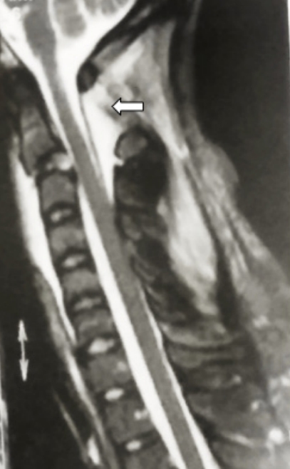
Sagittal magnetic resonance image of a flexion type of Hangman’s fracture. Please note the increased C1–2 interspinous interval and the signal changes suggesting hematoma formation (white arrow).
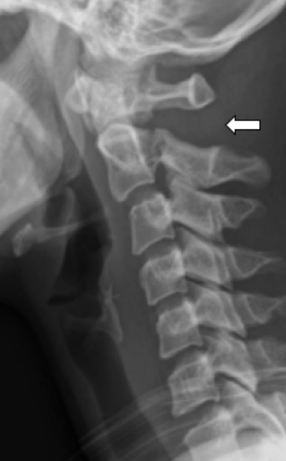
X-ray of a similar flexion type of Hangman’s lesion depicting the increased C1–2 interval suggesting disruption of the posterior ligament complex (white arrow).
The authors of this study propose an alternate hypothesis – the more common extension compression type of Hangman’s lesion is caused by a pincer like compression of the C2 pedicle between the inferior articular process of the C1 and the superior articular process of C3 (Fig. 11). The anatomical fact that the C1–2 facet is far anterior to the C2–3 facet perhaps results in the frequent running of the superior part of the fracture line into the vertebral body, often aggravated by the lateral flexion or rotated position of the head at the moment of impact. The flexion Hangman’s lesion, on the other hand appears to be a 3-point bending failure where the pedicle is bent over the fulcrum of the C3 superior facet (Fig. 12). Evidently, the position of the head in lateral flexion and rotation at the time of the insult would determine the precise nature of the injury. Gross and Benzel have postulated that the cervico-cranium and the subaxial spine are embryologically separated at the isthmus of the C2 vertebra making it vulnerable to injury [3]. This developmental model has been supported by Gebauer and Amling [39]. They also use the C3 body chip fracture at the antero-rostral body and the kyphosis of the C2–3 junction as the indicators for the flexion injuries. The present authors do not support this view entirely but use additional radiological parameters, particularly evidence of tensile failure of the PLC at C1–2 as evidence of flexion type of Hangman’s injury [40,41]. The criteria for diagnosis of the flexion injury are illustrated in earlier publications by the author. Semantic, though these discussions might appear, it may have significant clinical applications. Since the pertinent biomechanical principle by which internal fixation in the spine works is the “tension band principle,” in the flexion injury with PLC failure at C1–2 would mandate a C1–3 posterior fixation (or preferably C1–2 fixation where the C2 screw crosses the pars fracture line), and in the extension injury an anterior C2–3 discectomy and fusion. In the latter lesion if the posterior approach is chosen the extent of fixation is therefore C2–3 levels. It is the author’s opinion that the flexion Hangman’s lesion is an entity where the PLC of C1–2 vertebrae are disrupted if surgery is mandated, the C1–2 level must be included in the posterior stabilization procedure.
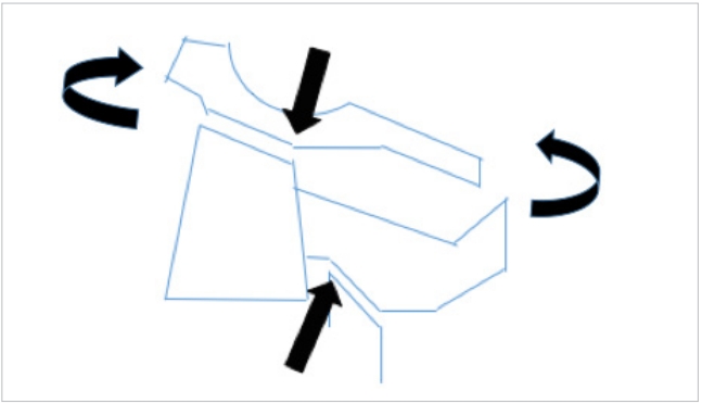
Possible mechanism of the extension type of Hangman’s injury. The curved arrows depict the extension moment and the straight arrows the pincer effect of the facets on the isthmus.
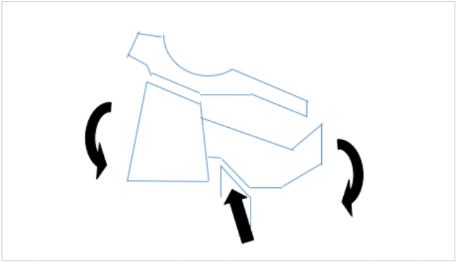
The flexion type of Hangman’s injury is possibly the result of a 3-point bending moment as illustrated here. The Axis is bent over the fulcrum of the C3 superior facet creating the isthmus fracture.
CONCLUSION
Based on detailed study of the trabecular anatomy and distribution in the Axis vertebra the authors have proposed an internal gear mechanism of load distribution in the bone. They also propose a leaf spring model which explains why the C2 pedicle is particularly vulnerable to injury. The flexion type of Hangman’s lesion is to be clearly differentiated from the extension type of injury for if surgery is indicated for the former, C1–2 posterior stabilization becomes mandatory to comply with tension band principles. The more common extension type of injury can be stabilized by C2–3 fixation, either anteriorly or posteriorly.
Notes
The authors have nothing to disclose.
Acknowledgements
This paper was presented at the APCSS meeting at New Delhi, in November 2018.