The Intersection Between Lateral Mass and Inferomedial Edge of the C1 Posterior Arch: A Reference Point for C1 Lateral Mass Screw Insertion
Article information

Abstract
Objective
To determine the ideal Atlas (C1) lateral mass screw placement and trajectory using the intersection between the lateral mass and inferomedial edge of the posterior arch as an easily identifiable and reproducible medial reference point. Selection of an ideal entry point and trajectory of C1 lateral mass screw insertion can help to minimize neurovascular injuries. While various techniques for screw insertion have been proposed in the past, they all require extensive dissection of the C1 lateral mass, which can cause profuse bleeding.
Methods
Ninety-three 3-dimensional computed tomography reconstructed images of C1 lateral masses in adult patients were utilized to simulate the placement of C1 lateral mass screws via 4 entry points and 2 trajectory angles referencing off of a medial reference point using Vero’s VISI 17 software. The safety during screw insertion simulation, as well as the screw length, were evaluated.
Results
We found that C1 lateral mass screws could be safely placed bilaterally at 3 mm lateral to the reference point in both 0° and 15° medial screw angulation without violation of the cortex. The 15° medial angulation allowed for longer (18 mm) screws than the 0° angulation.
Conclusion
We recommend starting C1 lateral mass screws 3 mm lateral to the intersection between the lateral mass and inferomedial edge of the posterior arch at a 15° medial angulation.
INTRODUCTION
Atlas (C1) lateral mass screw fixation is widely used to stabilize the atlantoaxial (C1–2) joint in posterior C1–2 screw-rod constructs. The C1 lateral mass screw and plate were first described by Goel et al. [1] in 1994 and modified for C1 polyaxial screw-rod systems by Harms and Melcher [2] in 2001. Many clinical reports of this technique have demonstrated biomechanical strength comparable to C1–2 transarticular screw fixation [3-6], but with a minimization of the risk of vertebral artery injury and occipitocervical (C0–1) joint injury. While techniques for C1 lateral mass screw insertion have been proposed in the past, several require an extensive dissection of the entire posterior C1 lateral mass to identify the entry point [1,2,7,8]. This can increase operative time and cause copious bleeding from a venous sinus injury in the C1–2 complex [1,2,8-10]. A reproducible and easily identified optimal entry point and trajectory for C1 lateral mass screw insertion may help to minimize this complication.
This computed tomography (CT) study aims to identify the ideal starting location from an easily identifiable and reproducible reference point, the intersection between the lateral mass and the inferomedial edge of the C1 posterior arch. We sought to determine the ideal trajectory and unicortical intraosseous screw length at each entry point.
MATERIALS AND METHODS
1. Study Design
Cervical spine CT images with 1 mm cut from 93 consecutive adult patients from March 2016 to January 2017 were utilized. Approval from the Institutional Ethics Board of Research Ethics Committee, Chiang Mai University (ORT-2559-04158) was obtained before initiation of the study. Exclusion criteria were patients younger than 18 years, as well as anyone with C1 anatomical abnormalities due to conditions such as tumor, infection, rheumatism, trauma, or any other defects. The Digital Imaging and Communications in Medicine format from the CT images was processed to stereolithography (STL) format using Mimics software (Materialise HQ, Leven, Belgium). The actual dimension included the core and thread diameters of the 4.0-mm C1 lateral mass screw was also simulated by Mimic software. The STL 3-dimensional (3D) data from C1 and the screws were virtually placed and analyzed using Vero software (Vero’s VISI 17, CAD/CAM/CAE software solutions, Cheltenham, UK).
2. Entry Point and Trajectory Assessment
The C1 vertebrae were standardized using the symmetry of the transverse process and the posterior arch in both the coronal and transverse planes. Virtual placement of 4.0-mm C1 lateral mass screws was performed bilaterally at 4 entry points and 2 trajectory angle parameters. The reference point was set at an intersection between the lateral mass and the inferomedial edge of the C1 posterior arch in the transverse plane (Fig. 1A), and the inferior border of the posterior arch in the sagittal plane (Fig. 1B). The lateral entry points were determined at 3 mm, 5 mm, and 7 mm lateral from the reference point in the axial plane (Fig. 1C). The simulated screw placement was performed parallel to the plane of the posterior arch of C1 in the sagittal plane and both 0° and 15° medial trajectory angles at each entry point (Fig. 1D). The ideal end position was set at the point located 2 mm behind the anterior cortex of the C1 lateral mass.
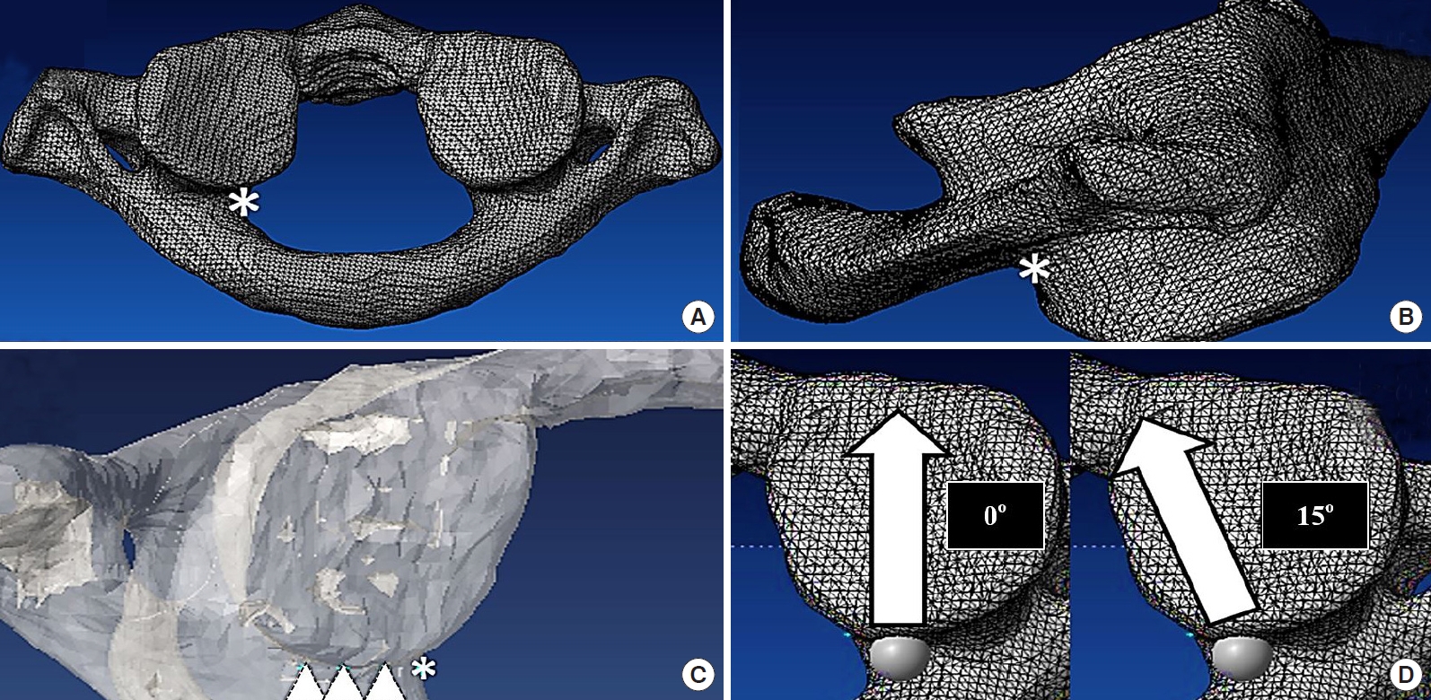
The reference point was set at the intersection between the lateral mass and the inferomedial edge of the C1 posterior arch (asterisk) in the axial plane (A) and just caudal to where the posterior arch intersects with the lateral mass in the sagittal plane (asterisk) (B). (C) The lateral entry points were determined to be 3 mm, 5 mm, and 7 mm lateral to the reference point (asterisk) in the axial plane (triangles). (D) The axial view demonstrates the screw trajectory in both the 0° and 15° medial trajectory angles.
Violation of the cortex during simulated screw insertion was carefully evaluated in a 3D view. The percentage of screw breach at each entry point and trajectory was recorded. The screw breach distance was measured (Fig. 2A) and graded by the Gertzbein and Robbins grading system; grade 0: no breach, grade 1: breach distance < 2 mm, grade 2: breach distance 2-4 mm, grade 3: breach distance > 4 mm [11]. The interosseous screw length at each entry point and trajectory was also measured (Fig. 2B).
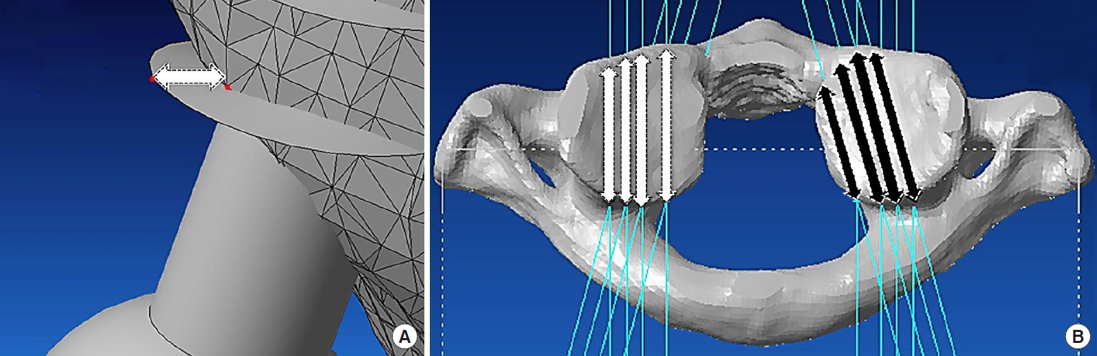
(A) Measuring and grading the screw breach distance. (B) Measuring the intraosseous screw length with the simulated screw tip 2 mm short of the anterior cortex of the C1 lateral mass in the 0° (white arrows) and 15° (black arrows) medial trajectory angle.
3. Statistical Analysis
The intraosseous screw length was calculated by using the mean ± standard deviation. All data were tested for their normality using the Shapiro-Wilk test. A paired t-test was used to analyze the mean intraosseous screw length between 0° and in 15° medial angulation and the Student t-test was used to analyze the mean intraosseous screw length between males and females. Statistical analysis was performed using the IBM SPSS Statistics ver. 20.0 (IBM Co., Armonk, NY, USA). The level of statistical significance was set at 0.05.
RESULTS
There were 55 men and 38 women in the study. A 4.0-mm C1 lateral mass screws could be safely placed bilaterally starting at 3 mm lateral to the reference point in both the 0° and 15° medial angulation. At the entry point located 5 mm lateral to the reference point, the C1 lateral mass screw could also be placed in the 15° medial angulation without any cortical violation (Table 1). However, at other entry points and directions, the screw may breach the lateral mass cortices.
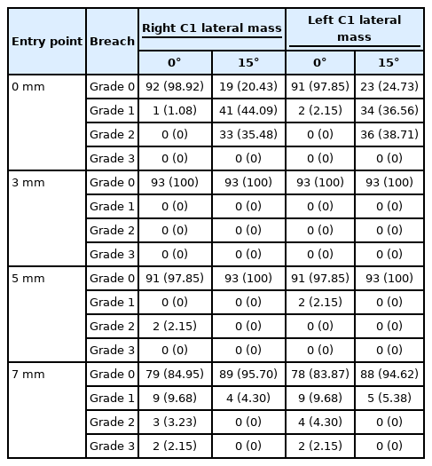
Percentage of safe screw placement at each entry point and trajectory
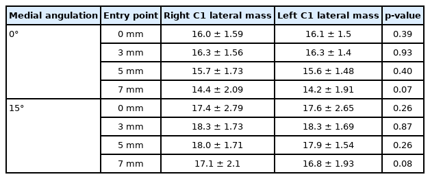
The mean intraosseous unicortical screw lengths at 3 mm lateral to the reference point were approximately 16 mm in 0° medial angulation (16.3 ± 1.57 mm at the right lateral mass and 16.3 ± 1.40 mm at the left lateral mass) and 18 mm in 15° medial angulation (18.3 ± 1.73 mm at the right lateral mass and 18.3 ± 1.69 mm at the left lateral mass), respectively. At 5 mm lateral from the reference point, the optimal screw length was approximately 18 mm in 15° medial angulation (18.0 ± 1.71 mm at the right lateral mass and 17.9 ± 1.54 mm at the left lateral mass) (Table 2). A paired t-test was used to analyze the mean intraosseous screw length between 0° and in 15° medial angulation. The mean intraosseous screw length was significantly longer in 15° medial angulation than in 0° medial angulation at every entry point (p < 0.001) (Table 3). Student t-test was used to analyze the mean intraosseous screw length between males and females. There was significantly longer in males than in females at almost every entry point and trajectory—except in 15° medial angulation at the reference point (p < 0.05) (Table 4). There was no difference in the mean intraosseous screw length in the right and left lateral masses in our study (Table 5). Detailed results and analysis of the data are summarized in Tables 1–5.

Mean intraosseous screw length (mm) at each entry point and trajectory
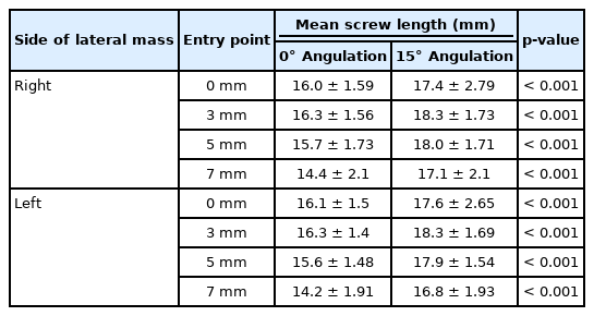
The difference in mean intraosseous screw lengths between 0° and 15° medial angulation

The difference in mean intraosseous screw length (mm) between males and females
The difference in mean intraosseous screw length (mm) between right and left lateral mass
DISCUSSION
C1 lateral mass screw placement can be technically demanding and poses risk of injury to major neurovascular structures, including the spinal cord and the vertebral artery [12]. Numerous complications have been reported, including lethal bleeding from a large venous sinus injury [1,10,13], vertebral artery injury, violation of the occipitocervical (C0–1) joint, internal carotid injury [14,15], and hypoglossal nerve injury [15,16]. However, the C1 lateral mass screw can be safely placed with careful attention to the anatomy and using lateral fluoroscopic guidance [17]. One of the most challenging steps of C1 lateral mass screw insertion is avoiding and minimizing the bleeding from the large venous sinus overlying the C1–2 joint during dissection [1,10].
1. Entry Point
Numerous optimal entry points and the screw trajectories for C1 lateral mass screws have been reported on [1,2,7,13,18]. Goel et al. [1] defined the entry point as being the center of the posterior surface of the lateral mass, 1–2 mm above the articular surface. Harms and Melcher [2] defined the entry point to be the middle of the junction of the C1 posterior arch and the midpoint of the posterior inferior part of the C1 lateral mass. Hong et al. [7] recommended that the entry point should be the intersection of the inferior border of the posterior C1 arch and the midpoint of the posterior aspect of the C1 lateral mass. Simsek et al. [19] stated that the midline of the lateral mass at the intersection of the posterior arch and the C1 lateral mass was the ideal entry point. These recommended entry points for C1 lateral mass screws are at the midpoint of the posterior surface of the lateral mass that is usually covered by a large venous plexus (formed by the anastomosis between the suboccipital cavernous sinus, vertebral plexus, posterior condylar emissary vein, and the sigmoid sinus) [20]. Injury to this venous plexus during exposure of the C1 lateral mass borders can cause profuse and even lethal bleeding, extend the operative time and cause the surgeons to alter their plans [21]. A revised technique, starting the screw from the posterior arch [18,22,23] is one simple way to avoid injury to the venous plexus. However, posterior arch screws can put the vertebral artery at risk, result in an arch fracture in small, thin patients, and are not always anatomically feasible in such patients [24].
In our study, an easily identifiable reference point was set at the intersection between the lateral mass and inferomedial edge of the posterior arch (Fig. 3A). Using this reference point, there is no need to dissect the entire posterior aspect of the C1 lateral mass, which can minimize the risk of venous plexus injury.
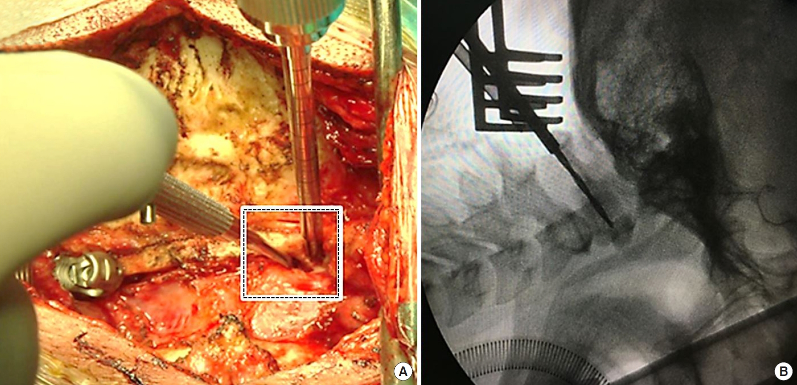
(A) The reference point from our study (square) is easily visualized and identified using a Penfield dissector intraoperatively. (B) The craniocaudal screw trajectory is parallel with the plane of the C1 posterior arch, which is easily visualized using intraoperative lateral fluoroscopy.
2. Trajectory
In the sagittal plane, the craniocaudal screw trajectory was determined to be parallel with the plane of the C1 posterior arch to avoid injury to the occipitocervical joint and the atlantoaxial joint, as mentioned by numerous authors [1,2,25-27]. We can easily obtain this direction intraoperatively using lateral fluoroscopy (Fig. 3B). In the axial plane, the 0° and 15° medial angulation screw trajectories were selected to maximize the margin of safety with the medial angulation trajectory. The unicortical C1 lateral mass screws were used because they can provide an equivalent pullout strength with a much lower risk of injury than the longer bicortical screws placed in a similar orientation [28].
3. Optimal Entry Point and Medial Trajectory
We found that the ideal entry point of a 4-mm C1 lateral mass screws is 3 mm to the reference point (which is the intersection between the lateral mass and inferomedial edge of the posterior arch). At this entry point, the screw can be safely placed in both the 0° and 15° medial angulation trajectories without any cortical violation. This starting point makes it unnecessary to dissect further laterally, minimizing the bleeding risk.
Hong et al. [7] described the relationship between the reference point in our study and the midpoint of the lateral mass, which is not the midpoint of the posterior surface of the lateral mass. They described the mean distance between the midline of the C1 lamina to the midpoint of the C1 lateral mass as 17.6 ± 1.2 mm; the mean distance between the midline of the C1 lamina to the inner edge of the C1 lateral mass was 14.2 ± 1.2 mm. They found that the center of the C1 lateral mass was, on average, 3.4 mm lateral to the inner edge of the C1 lateral mass. Al-Habib et al. [27] found that the midpoint of the C1 lateral mass was lateral to the medial edge of the C1 posterior arch by a mean of 1.42 ± 0.87 mm. Su et al. [29] stated that the midpoint of the lateral mass, which was the proper screw “start-point,” was 1.6 ± 1 mm lateral to the medial wall of the C1 pedicle. We believe that 3 mm lateral to our reference point is the ideal entry point because, according to previous studies, it is at the center, or just lateral to the center of the C1 lateral mass. This is in contradiction to a study by Blagg et al. [25], who suggested that the C1 lateral mass screw was best placed at the medial border of the posterior arch and its junction with the lateral mass. In our study, at the same point, the proportion of the screw breach is approximately 1%–2% in the 0° medial angulation and 74%–79% in the 15° medial angulation. The results of our study suggest that the medial border of the posterior arch may be too medial to be an appropriate starting point.
4. Intraosseous Screw Length
Several medial trajectory angles have been suggested in a number of published studies. Rocha et al. [20] found that the mean maximum medial angulation was 16.7° ± 1.3° (range, 14.6°–20.7°). Hong et al. [7] stated that the medial screw angulation was approximately 14.7° (left, 14.7° ± 2.9°; right, 14.7° ± 3.1°) and Simsek et al. [19] suggested that the ideal medial angulation was 13.5° ± 1.9° and the maximal medial angulation was 29.4° ± 3.0°. According to our results, a 15° medial angulation is an ideal trajectory because it permits a significantly longer screw, which is associated with a better biomechanical pullout strength [30]. In this direction, the screw can be safely inserted at both 3 mm and 5 mm lateral to the reference point. However, the head of the screws can sometimes impinge on the posterior arch. This might require that part of the posterior arch be notched to utilize this technique. Additionally, it may be necessary to use a longer screw for proper fixation with the rods when using this starting point.
To our knowledge, this is the first study to describe the relationship between C1 screw length and sex. As expected, the intraosseous screw length in males is significantly longer than in females. A study by Al-Habib et al. [27] found that the mean axial diameter of the C1 lateral mass was significantly larger in males than in females but did not comment on the length.
5. Limitations
As with all studies, ours is not without flaws. While we examined a large number of cases, human anatomy is infinitely variable and no recommended surgical starting point and trajectory can be safely utilized in 100% of cases. Rather, our recommended starting points and trajectory should be verified for each surgical patient to ensure that it works in that individual. Second, while it has been our experience that our starting point decreases venous bleeding, it does not eliminate it. The degree to which it decreases the bleeding is not within the scope of this paper and would require a prospective, randomized study. Third, this is a 3D CT simulation study. Therefore, while our paper may help provide some anatomical insights for surgeons, in a clinical situation, it may still be very difficult to find the exact same point intraoperatively.
CONCLUSION
Prior recommended starting points for C1 lateral mass screws are typically covered by a large venous plexus. Using the intersection between the lateral mass and inferomedial edge of the posterior arch, easily identified during surgery, as the starting point, obviates the need for further lateral dissection and thus avoids potentially bleeding. The ideal entry point for C1 lateral mass screws is 3 mm lateral to the reference point (the intersection between the lateral mass and inferomedial edge of the posterior arch). The screw direction should be parallel to the posterior arch of C1 in the sagittal plane. A 15° medial angulation in the axial plane is recommended because it can accommodate longer intraosseous screws.
Notes
K. Daniel Riew receives royalties from Biomet. He has done consulting work for Medtronic and Nuvasive. He is a stock holder with Amedica, Benvenue, Expanding Orthopedics, Nexgen Spine, Osprey, Paradigm Spine, Spinal Kinetics, Spineology, Vertiflex, PSD and Axiomed. He is a board member on the Global Spine Journal. For the remaining authors, none were declared.
Acknowledgements
The study was supported by Faculty of Medicine, Chiang Mai University, Chiang Mai, Thailand.