Finite Element Analysis of the Biomechanical Effect of Coflex™ on the Lumbar Spine
Article information
Abstract
Objective
The biomechanical properties of the Coflex™ (Paradigm Spine, NY, USA), a device designed to provide dynamic stabilization without lumbar fusion, have not been clearly defined. The purpose of this study was to determine the efficacy and biomechanical effect of Coflex™ using finite element model (FEM).
Methods
A 3D geometric model of the L3-L5 was created by integrating computerized tomography (CT) images. Based on the geometric model, a 3D FEM was created and the Coflex™ model was incorporated into the base model. Mechanical load dependent on the postural changes and boundary conditions, were imposed to simulate various 3D physiological states. The simulation analysis included stress and strain distributions, intervertebral disc deformation, and the range of motion of the facet joint and lumbar spinous process.
Results
Coflex™ significantly restrained displacement in extension, lateral bending and compression of joint between the L4-5 as one in the experimental group was observed -1.3% of flexion, -24.5% of extension, -44.5% of lateral bending and -37.2%. The average intradiscal pressure of the L4-5 decreased by 63% and the average facet contract force of the L4-5 decreased markedly by 34% in the experimental group. A load of 120 MPa from extension was observed at the base of spinous process in the experimental group.
Conclusion
The Coflex™ can be safely used for achieving functional dynamic stabilization of the lumbar vertebral column while preserving the intactness of the other components. However, the fatigue fracture of the L4 spinous process should be carefully monitored.
INTRODUCTION
The use of dynamic stabilization has increased due to its advantage of minimal invasiveness and preservation of motion range comparing to rigid stabilization8,15). Various methods of dynamic stabilization include facet joint replacement, pedicle screw and semi-rigid rod system installation and interspinous fixation. Among them, the interspinous fixation is most widely used, for it is the least invasive and is relatively simple to use8). Furthermore, insertion of interspinous implant between the spinous processes of the lumbar spine is expected to reduce back pain and prevent recurrence of herniated lumbar disc as it diminishes the force applied to the posterior part of the intervertebral disc as well as the facet joints8). Therefore, numerous interspinous implants have been developed since Knowles' study in 1950s9). However, it has been reported that the use of interspinous implants are often accompanied by postoperative complications, such as device migration, spinous process fracture and implant breakage3,5,6). In addition, its effectiveness and application have been questioned. Consequently, careful analysis of biomechanical characteristics of interspinous implants is in demand to validate its effectiveness and to avoid potential complications1,6,7).
In this study, we used a finite element modeling (FEM) study to elucidate the biomechanical effects of interspinous fixation using a specific interspinous implant device, known as Coflex™, and to determine the better strategy in the treatment of patients who require dynamic stabilization.
MATERIALS AND METHODS
1. Construction FEM model
To model a 3-D geometry of the spine, computerized tomographic (CT) scans of the lumbar spine in a healthy adult was used after obtaining a patient's informed consent. A customized volume mesh was generated by a homemade mesh generation program using Autodesk 3D Max 2010 (Autodesk, Inc., CA, USA) and MATLAB (MathWorks, MA, USA). The COMSOL Multiphysics (COMSOL Inc., MA, USA) was used to stimulate the developed spine model (Fig. 1). The finite element model of each spine consists of a vertebral body, endplate, intervertebral disc, facet joint, anterior longitudinal ligament, posterior longitudinal ligament, and facet-joint capsule. The vertebral bodies were made of outer cortical bone (1mm thick) and inner trabecular bone, and the superior and inferior surfaces were covered by endplates (1mm thick). The endplate was arranged to cover the superior and inferior surfaces of the intervertebral disc. The intervertebral disc was composed of a nucleus pulposus and an annulus fibrosus. The nucleus pulposus was set to occupy 50% of the total surface area of the disc and its height was 1 cm. The nucleus pulposus was designed to approximate the incompressible continuum with the modulus elasticity of 1MPa, and the annulus fibrosus was designed to have 8 layers. All of the vertebral body, the endplate and the intervertebral disc were assembled as the constraints defined as interlacing surface. The facet joint surface was defined as a frictionless, non-linear contact. The ligament was modeled to have only tension. The properties of all elements were assigned as listed inTable 1.
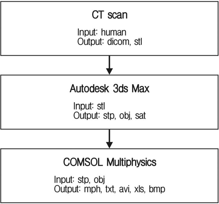
Scan to model workflow. A CT scan of a healthy 24-year-old male lumbar spine was used to develop the geometry for the model. Autodesk 3ds Max was used to convert dicom to mph files. Finally, COMSOL Multiphysics performed a finite element analysis of this model. Abbreviations (DICOM: digital imaging and communications in medicine, STL: standard template library, STP: standard for the exchange of product model data, OBJ: object file, SAT: standard ACIS text, MPH: multiphysics model file, TXT: text file, AVI: audio video interleave file, XLS: excel file, BMP: bitmap file).
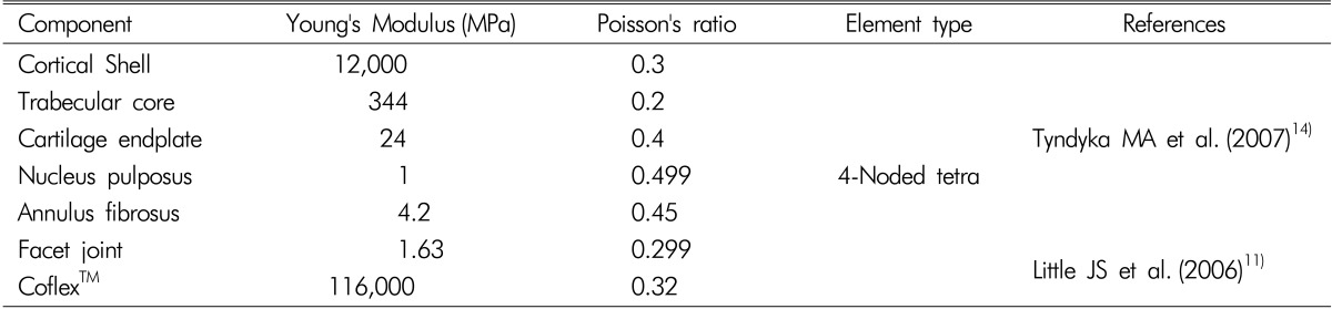
Material properties and elements assumed for the constitutive parts of the intact and Coflex™ implanted models.
2. Construction of Coflex™-implant FEM model
The L4 segment was selected to have the insertion of Coflex™ between the spinous processes of L4 and L5. Coflex™ was modeled to have mechanical properties of titanium (Ti6A14V). Four wings of Coflex™ were designed to fit in upper and lower spinous processes. The contact surface between Coflex™ and the spinous process were modeled to have frictional resistance. During an actual medical procedure, a laminectomy is often performed prior to the insertion. However, to simplify the modeling, Coflex™ was designated to be inserted without performing a laminectomy in this study.
3 Boundary and loading conditions
The fixed boundary condition restrained the inferior surface of the L5 segment in both the control and experimental groups. The simulation was carried out by applying force rather than displacement on the most upper part of the spine model in both groups. A compressive load of 500 N and 10 Nm of momentum were applied on the superior surface of the L3 to generate compression, flexion, extension, and lateral bending. In this study, range of motion (ROM), intradiscal pressure, peak facet contact force, peak spinous process contact force, and peak implant contact force were examined in those 4 motions generated.
RESULTS
1. Validation of FEM model
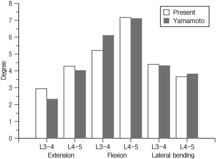
The models in both the control group and the Coflex™-implanted experimental group were validated before analysis of the result. The ROM results measured from the experimental group were compared with earlier biomechanical results from cadavers. The ROM results from this study showed similar results with those from cadavers that were studied by Yamamoto (Fig. 2)16). The difference between this study and Yamamoto's study was within the range of 0.4-17.8%. The difference is considered to occur due to the difference between the subjects used to design the models.
2. Range of motion
Coflex™ significantly restrained displacement in extension, lateral bending and compression of joint between L4-5 as one in the experimental group was observed -1.3% of flexion, -24.5% of extension, -44.5% of lateral bending and -37.2% of compression compared to the control group. Joint between L3-4 in the experimental group resulted in -3.3% of flexion, -0.7% of extension, -0.02% of lateral bending and -4.1% of compression comparing to the control group, however, Coflex™ did not affect ROM of other segments (Fig. 3).

Comparison of the predicted range of motion between the intact and Coflex™ implanted models during flexion, extension, and lateral bending at the level of L3-4 and L4-5.
3. Change of intradiscal pressure
The changes in intradiscal pressure in both the experimental and control groups were estimated from finite element analysis (Fig. 4). The average intradiscal pressure of joints between L4-5 in the experimental group decreased by 63%, and each of flexion, extension and lateral bending decreased by 25%, 72%, and 53% respectively. Therefore, Coflex™ was considered to be responsible for minimizing intradiscal pressure on L4-5 during extension and lateral bending. In addition, a decrease in intradiscal pressure at the posterior annulus fibrosus was observed in the experimental group as a result of von Mises stress (Fig. 5).
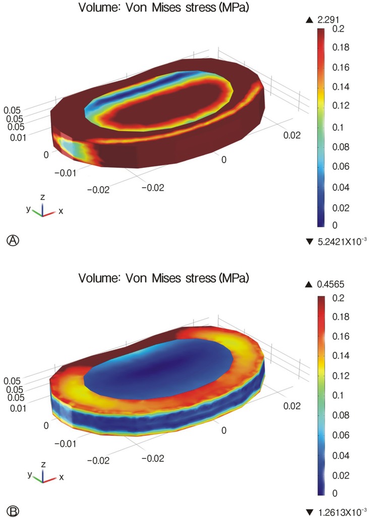
Von Mises stress distributions of the annulus fibrosus at L4-L5 during extension between intact (A) and Coflex™ implanted models (B). A. L4-5 intervertebral disc of intact model. B. L4-5 intervertebral disc of Coflex™ implanted model.
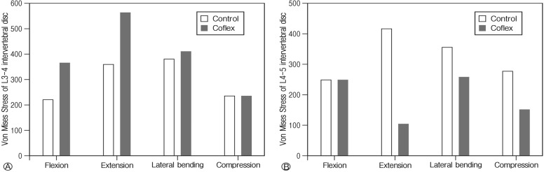
Comparison of the predicted average intradiscal pressure between the intact and Coflex™ implanted models during flexion, extension, lateral bending, and axial rotation at the level of L3-4 (A) and L4-5 (B).
4. Peak facet contact force on facet joints
The facet contact forces were measured in all of the motions except flexion. The peak facet contact forces for both of the experimental and control groups were demonstrated in Fig. 6. The average facet contract force on joint between L4 and 5 decreased markedly by 34% in the experimental group, and it was 7%, 23%, and 7% in extension, lateral bending, and compression, respectively. The average facet contract force on joint between L3 and 4 increased by 129% in the experimental group, and it was 170%, 145%, and 101% in extension, lateral bending, and compression, respectively.

Comparison of the predicted peak facet contact forces between the intact and Coflex™ implanted models during flexion, extension, lateral bending, and axial rotation at the level of L3-4 (A) and L4-5 (B)
5. Peak spinous process and implant contact force
A load of 120 MPa from extension was observed at the base of spinous process in the experimental group in which Coflex™ was inserted, and it verified that stress was intensive there. This result seems to be reasonable as the most common site of fracture occurs on the base of spinous process in follow up periods.
DISCUSSION
This study analyzed the biomechanical effects of the interspinous soft fixation with Coflex™ at the segments of L3-4 and L4-5; it was found that Coflex™ was not responsible for the intradiscal pressure of the adjacent segments. Rather, the Coflex™ inserted into segment of L4-5 resulted in a decreased force on the posterior part of the intervertebral disc and facet joint in extension. This study agrees with previous studies, which have asserted that Coflex™ insertion reduces ROM in flexion and extension, but does not affect ROM at the adjacent segments4,10,12,13). However, Coflex™ did increase facet loading on the adjacent levels.
According to this study, the decreased intradiscal pressure in compression and extension was largely observed in the posterior annulus. The pain generators in spine are sinuvertebral nerve in the posterior annulus and medial branches in the facet joints. Consequently, diminution of force on the posterior annulus and of pressure on the facet joint is expected to reduce pain after procedure to some extent2,10,12). Furthermore, if the posterior annulus is injured by discectomy, the decreased loading on it may contribute to prevent recurrence10,12). Further, the effect of Coflex™ on restraining spine motion is thought to improve spinal instability that resulted from discectomy and laminectomy10,12). Although little increase in facet loading was observed, grossly little effects on the adjacent level may minimize the chance of adjacent level degeneration compared with conventional rigid fixation10,12). This has been proven in several clinical researches and shows the possibility of replacing conventional rigid fixation with interspinous soft fixation8,10,15). Besides these positive effects, the mount of Coflex™ generally increased the stress level on the facet joints of adjacent level in cases of extension and lateral flexion, and undesired stress can be applied on spinous process which, ifrepeated, can ultimately result in the fracture of spinous process. Also, the device itself is subject to large stress, especially on the bending portion, and fatigue fracture of the device is possible if a large stress is constantly applied to this portion. The fracture of the spinous process and mounting device has been previously reported. Reduction of space between spinous process of adjacent vertebral segments due to aging after many years, since the device was first implanted can lead to increment of stress on both spinous process and the device, increasing the chances of fractures higher3,5,6,8).
The present study has shortcomings in that it is based on numerical data obtained from computerized FEM simulations rather than actual measurements obtained from cadaveric study. Simplification of ligaments near spinal segments should be avoided in future studies, which should incorporate muscles and ligaments with mechanical properties and proper biomechanical characteristics accompanied by cadaveric experiments.
CONCLUSION
The results of the present model predict the effect of Coflex™ on the reduction of stress and strain on the posterior annulus and facet joints of the treated level in cases of extension and compression. In addition, it is postulated that Coflex™ can adversely concentrate the stress on the facet joints of the adjacent levels, the junction part of the spinous process, and the bending portion of the device. Thus, Coflex™ may lead to fatigue fracture of either spinous process or the device.
Acknowledgements
This study was supported by a grant of the Korea Healthcare technology R&D project, Ministry for Health & Welfare Affairs, Republic of Korea (A111016) and by a grant from the Institute of Medical System Engineering (iMSE) in the GIST, Korea.