A Biomechanical Comparison of 2 Different Topping-off Devices and Their Influence on the Sacroiliac Joint Following Lumbosacral Fusion Surgery
Article information

Abstract
Objective
Interspinous spacer (ISS)-based and pedicle screw-rod dynamic fixator (PDF)-based topping-off devices have been applied in lumbar/lumbosacral fusion surgeries for preventing the development of proximal adjacent segment degeneration. However, little attention has been paid to sacroiliac joint (SIJ), which belongs to the adjacent joints. Accordingly, the objective of this study was to compare how these 2 topping-off devices affect the SIJ biomechanics.
Methods
A validated, normal finite-element lumbopelvic model (L3–pelvis) was initially adjusted to simulate interbody fusion with rigid fixation at the L5–S1 level, and then the DIAM or BioFlex system was instrumented at the L4–5 level to establish the ISS-based or PDF-based topping-off model, respectively. All the developed models were loaded with moments of 4 physiological motions using hybrid loading protocol.
Results
Compared with the rigid fusion model (without topping-off devices), range of motion and von-Mises stress at the SIJs were increased by 23.1%–64.1% and 23.6%–62.8%, respectively, for the ISS-based model and by 51.2%–126.7% and 50.4%–108.7%, respectively, for the PDF-based model.
Conclusion
The obtained results suggest that the PDF-based topping-off device leads to higher increments in SIJ motion and stress than ISS-based topping-off device following lumbosacral fusion, implying topping-off technique could be linked to an increased risk of SIJ degeneration, especially when using PDF-based device.
INTRODUCTION
Lumbar/lumbosacral fusion with posterior stabilization is a widely accepted surgical procedure for the treatment of patients with symptomatic lumbar disc disease. However, the patients frequently suffer from adjacent segment degeneration (ASD) after fusion. Nearly 30% of cases have been reported to develop radiological ASD after fusion, and roughly a quarter to a third of these ASD cases may progress to clinical diseases that cause pain or numbness, eventually requiring additional surgery [1]. From a biomechanics perspective, the use of implants in fusion surgery, such as intervertebral cage and rigid fixator, can cause increased stiffness and thus result in load redistribution at neighboring levels. As a result, adjacent segments experience increased mobility and stress, which can contribute to the ASD development [2-4]. By considering this evidence associated with ASD, the dynamic implants made of more compliant materials were developed to establish stabilization and load-bearing capacity, while also allowing moderate motion in the instrumented segments [5,6]. Recently, the topping-off technique involving a combination of rigid fusion and dynamic implants, as illustrated in Fig. 1, has been proposed to reduce the ASD risk, and favorable clinical and radiological outcomes have been reported [7-9].
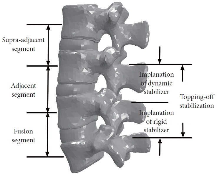
A graphical representation depicting the application of topping-off technique in fusion surgery.
The dynamic implants used for topping-off stabilization are typically categorized into 2 types: interspinous spacer (ISS) and pedicle screw-rod dynamic fixator (PDF). Several published studies have compared these 2 topping-off techniques in terms of the clinical and biomechanical effects. For example, a retrospective controlled study of Fuster et al. [10] reported that the percentages of patients suffering from adjacent segment disease were 6.1% and 4.2% in the ISS-based and PDF-based groups, respectively, which were lower than in the fusion alone group (20%). Finite-element (FE) studies of Lee et al. [11] and Fan and Guo [12] reported that the PDF-based device led to a lower range of motion (ROM) at the adjacent segment as compared to the ISS-based device, and such differences could impact the probability of developing ASD over time. Despite the valuable insights provided by these previously published works, most of them concentrated on the proximal segment neighboring the fusion, and little attention has been paid to sacroiliac joint (SIJ).
SIJ is the joint between the pelvis and the sacrum. Functionally crucial, the SIJ plays a vital role in providing stability and facilitating load transfer from the lumbar spine to the lower extremities [13,14]. It has been suggested that SIJ may be responsible for chronic lower back pain in around 13% to 30% of patients who have undergone lumbar/lumbosacral fusion [15]. According to clinical research, fusion procedures have been found to expedite the process of SIJ degeneration, especially in the lumbosacral fusion group, where SIJ degeneration developed more often and revealed more rapid and more severe progression than in the lumbar group [16,17], potentially resulting in the SIJ-related pain [18]. From a biomechanics perspective, it is possible that SIJ degeneration may be caused by the increased motion and stress resulting from fusion [19,20], similar to how the ASD occurs in lumbar spine. Moreover, a recent biomechanical study of the current authors [21] suggested that the risk of SIJ degeneration was further increased when supplementing the lumbosacral fusion with topping-off instrumentation. However, the biomechanical differences between different topping-off devices still remains unclear. Accordingly, this study aimed to continue to compare biomechanical effects of 2 most common topping-off devices, ISS-based and PDF-based topping-off devices, on SIJ following lumbosacral fusion based on our previous study. We focused on analyzing the ROM and von-Mises stress at the left and right SIJs using FE method.
MATERIALS AND METHODS
A previously validated, normal FE lumbopelvic model (L3–pelvis) [21] was utilized to simulate the topping-off surgery in this study (Fig. 2). The geometry of this initial model was derived from computed tomography (CT) images of a healthy adult female (the use of CT scans to derive the geometry was approved by biological and medical ethics committee of Northeastern University with reference number NEU-EC-2022B003S), which was then meshed using ANSA software (BETA CAE Systems S. A., Thessaloniki, Greece). The cancellous bone in the pelvis and vertebrae was enclosed by cortical bone with a thickness of 1 mm and 0.7 mm, respectively. The intervertebral disc was composed of a nucleus pulposus and an annulus ground substance containing fibers. The left and right SIJs were modeled as thin elastic layers between the sacrum and iliac bone. All the ligaments were represented using tension-only truss elements. Material properties for various components within the model were obtained from published literature (Table 1) [22-25]. A detailed description regarding the processes of model development and validation can be found in our previous studies [21,26].
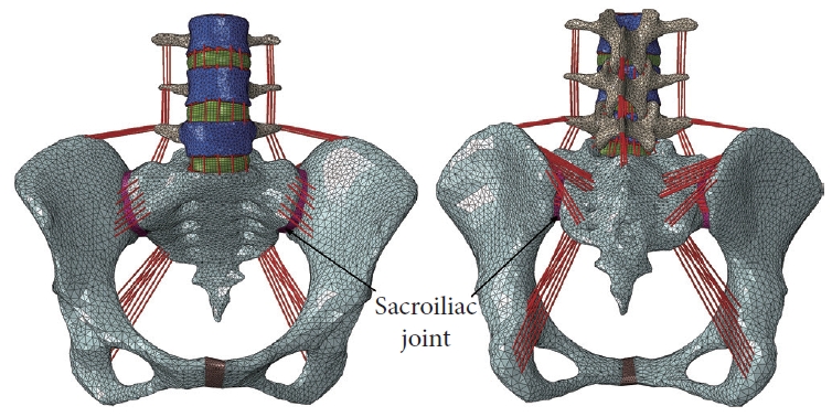
Front and rear views of the normal finite-element lumbopelvic model.

Material properties of the developed finite-element models
1. FE Model of the Topping-off Surgery
The normal L3–pelvis model was modified to simulate lumbosacral fusion by initially performing unilateral facetectomy and partial discectomy on the L5–S1 segment, and subsequently implanting a polyetheretherketone intervertebral cage (packed with autologous bone grafts) and a titanium pedicle-screw-rod fixation system (Fig. 3). Afterwards, DIAM (Medtronic Inc., Minnesota, MN, USA) system or BioFlex (Bio-Spine Corp., Seoul, Korea) system was instrumented at the L4–5 level of the lumbosacral fusion model to generate the ISS-based or PDF-based topping-off model, respectively (Fig. 4). DIAM, an “H”-shape silicone bumper wrapped with a polyester, was placed between the L4–5 spinous processes where the interspinous ligaments were removed (Fig. 4A). BioFlex consists of 4 titanium pedicle screws inserted into L4 and L5 vertebral bodies and 2 coiled-shape flexible nitinol connecting rods (Fig. 4B). All the interfaces between the bones and implants were assumed to have full bonding via node sharing, and material properties for the implants are also given in Table 1.

Finite-element modeling of the lumbosacral fusion. (A) Rear view of the fusion segment. Removal of the left facet joints, entire nucleus and the left posterior annulus fibrosus. (B) Position of the intervertebral cage. (C) Position of the titanium pedicle-screw-rod fixation system (section view).
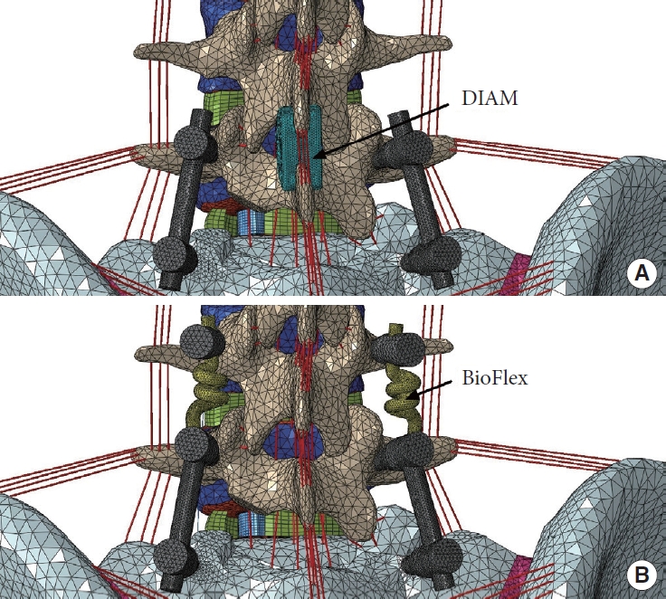
The lumbosacral fusion combined with different topping- off devices. (A) Interspinous spacer-based topping-off model using DIAM (Medtronic Inc., Minnesota, MN, USA) system. (B) Pedicle screw-rod dynamic fixator-based toppingoff model using BioFlex (Bio-Spine Corp., Seoul, Korea) system.
2. Boundary and Loading Conditions
Four FE lumbopelvic models were investigated: normal model, fusion model (without topping-off devices), ISS-based and PDFbased topping-off models. The developed models were fixed in all directions at the surfaces of left and right acetabula and were subjected to a 400 N compressive follower preload plus a moment in flexion, extension, lateral bending, and axial rotation (Fig. 5). A hybrid load control method was used to apply moments to the superior surface of L3 vertebra, which involved varying the applied moments for the surgical models until the angular motion of L3 vertebra equaled the normal model values [27]. The applied moments for the normal and surgical models are given in Table 2. The rationale behind this loading protocol is that patients, during their daily activity after surgery, continue to attempt to move their spine in a comparable manner to before. The FE computations were performed using ABAQUS software (Dassault Systems Simulia Corp., Providence, RI, USA), and the outcomes including ROM and average von-Mises stress at SIJs were analyzed and compared among the models.
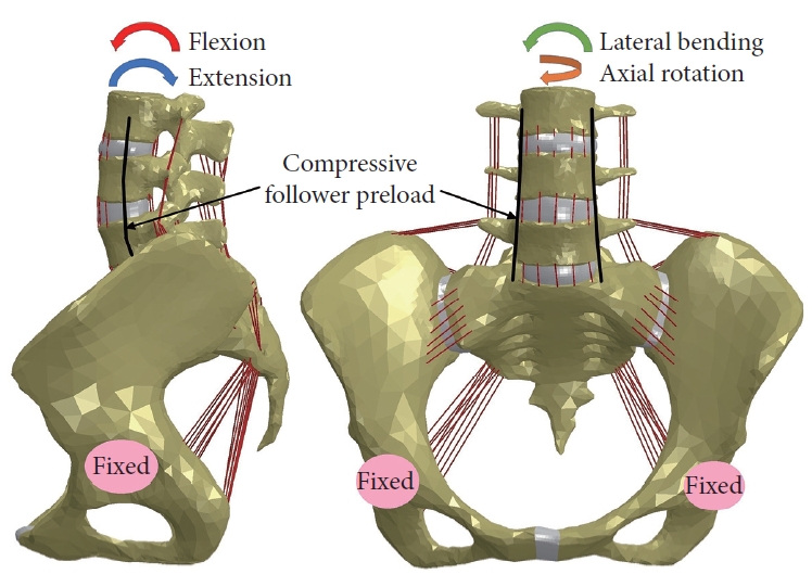
Boundary and loading conditions for the investigated finite-element models.

The hybrid moment applied in each model to produce the same angular motion of L3 vertebra
RESULTS
Fig. 6 compares the computed SIJ ROMs between the normal and surgical models. Overall, the ROM was the greatest in PDF-based topping-off model, followed by ISS-based topping-off model, fusion model, and normal model under all physiological loadings. Further, it was found that compared with the fusion model, the left and right SIJ ROMs were increased by 58.5% and 64.1% in flexion, 43.5% and 44.2% in extension, 23.1% and 33.3% in lateral bending, and 29.0% and 34.4% in axial rotation, respectively, for the ISS-based topping-off model; and were increased by 70.7% and 74.4% in flexion, 51.2% and 53.3% in extension, 107.7% and 126.7% in lateral bending, and 71.0% and 78.1% in axial rotation, respectively, for the PDF-based topping-off model.
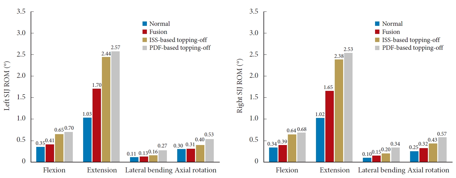
SIJ ROM for the investigated models under 400N compressive follower preload plus bending moment (hybrid protocol). SIJ, sacroiliac joint; ROM, range of motion; ISS, interspinous spacer; PDF, pedicle screw-rod dynamic fixator.
Fig. 7 compares the stress distribution in the SIJ between the normal and surgical models. The highest stress concentration at the SIJs was observed in PDF-based topping-off model, followed by ISS-based topping-off model, fusion model, and normal model under all physiological loadings. Further, it was found that compared with the fusion model, the left and right SIJ average stresses were increased by 60.1% and 62.8% in flexion, 42.0% and 42.6% in extension, 24.2% and 23.6% in lateral bending, and 24.0% and 25.8% in axial rotation, respectively, for the ISS-based topping-off model; and were increased by 68.6% and 70.5% in flexion, 50.4% and 50.7% in extension, 108.7% and 101.9% in lateral bending, and 62.3% and 64.8% in axial rotation, respectively, for the PDF-based topping-off model.
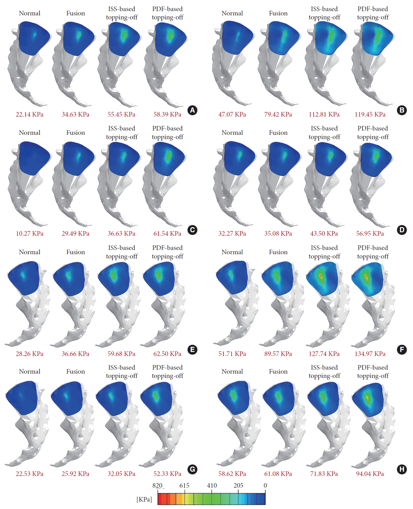
Von-Mises stress distributions at SIJs of the investigated models under 400 N compressive follower preload plus bending moments (hybrid protocol). (A) Left SIJ stress under flexion. (B) Left SIJ stress under extension. (C) Left SIJ stress under lateral bending. (D) Left SIJ stress under axial rotation. (E) Right SIJ stress under flexion. (F) Right SIJ stress under extension. (G) Right SIJ stress under lateral bending. (H) Right SIJ stress under axial rotation. Average value of the SIJ stress for each case were shown in red fonts. SIJ, sacroiliac joint; ISS, interspinous spacer; PDF, pedicle screw-rod dynamic fixator.
DISCUSSION
ISS-based and PDF-based topping-off devices have been applied to prevent proximal ASD after lumbar/lumbosacral fusion surgery. Many clinical and numerical studies have been conducted to determine the effects of topping-off instrumentation on the postsurgical lumbar spine. However, it still remains unclear how the different topping-off devices affect the biomechanical behaviors of SIJ following the fusion surgery, which is considered to be a source of persistent or new pain after fusion. Accordingly, this FE study was designed to address this issue.
According to available biomechanical studies, it appears that there is no significant biomechanical difference among various ISSs as well as among various PDFs [28,29]. Therefore, the DIAM and Bioflex models developed by the current authors before [12] were used in this study as the ISS-based and PDF-based topping-off devices, respectively. Considering the fact that the joint degeneration occurs during the long-term postsurgical period, the interfaces between the bones and implants were modeled as full bonding to simulate the biomechanical behavior of long-term effects after the fusion surgery. As demonstrated by previous researchers, a hybrid load control method could give results representing actual scenario in clinical cases following the surgical procedures and implantation, especially appropriate for biomechanical evaluation of the adjacent joints [27,30]. By employing this protocol, the examination of kinematic and mechanical compensation on the adjacent segments due to the implantation of the various devices is direct. Therefore, the hybrid protocol was used to apply the physiological loadings to the investigated models, and to evaluate the biomechanics of the SIJ that is one of neighboring joints.
It was observed from Figs. 6 and 7 that the lumbosacral fusion led to the increased ROM and stress at SIJs, which might be due to the kinematic and mechanical compensation from the fusion segment to SIJ. These results were consistent with the findings of previous cadaveric experimental and numerical studies [15,19,20], and could partially explain the clinical and radiographic observations reporting that the lumbosacral fusion surgery caused SIJ degeneration [16,17]. It was also observed that the ROM and stress were further increased after the topping-off instrumentation, which might be because the topping-off device increased stiffness of the instrumented segment and thus led to the increased kinematic and mechanical compensation to SIJ. It implies that the topping-off technique might increase the risk of SIJ degeneration. Furthermore, the computed results indicated that the PDF-based topping-off device led to larger ROM and stress at SIJs than the ISS-based topping-off device. This might be because the PDF device gave a higher stiffness to the instrumented segment, which can be proved by the fact that the PDF-based topping-off model required larger moment to achieve the same motion (Table 2), and thus incurring more kinematic and mechanical compensation to the SIJs. Overall, the fusion surgery has been proved to accelerate the process of degeneration in adjacent spinal segment and SIJ [1,16,17]. Previous studies have shown that the topping-off technique could help prevent degeneration of the adjacent spinal segment [7-9,11,24], especially the PDF-based topping-off devices which can give better protection to adjacent spinal segment [10,12]. However, the current authors have found that this technique may actually aggravate SIJ degeneration, especially when using the PDF-based devices. As with every coin having 2 sides, therefore the use and selection of topping-off techniques need to be carefully weighed according to a patient’s actual clinical symptoms.
Like other FE studies conducted in vitro, this study has several limitations. The constructed models may not fully capture the complexity of lumbar spine in vivo, primarily due to the inherent assumption and simplification. Firstly, the follower load technique was used to simulate muscle forces around the spine region due to lack of musculature in current in vitro FE models. However, follower load is a simplified load essentially (it represents the body weight and local muscles) [31], which was not able to completely reflect the physiological situation. In the future work, the current authors will try to create a more complete model incorporating lumbar and pelvis muscles to reflect realistic in vivo condition. Secondly, elastic, isotropic, and homogeneous material properties were assumed for the bone structures in the models due to a lack of available data. Despite the impact on the accuracy of stresses and loads, the overall pattern of the results would not change [32]. Thirdly, the geometrical model originated from a unique spine–pelvis specimen without considering the variation in geometry between individuals. Despite the computed absolute values might not be representative for an average person, they can demonstrate varying trends among different surgical cases. In addition, inserting ISS or pedicle screws mostly requires open surgery including a relatively large skin incision as well as detaching muscles from bone in clinical practice, therefore the development of a less invasive technique such as the development of percutaneously insertable/removable devices is desirable.
CONCLUSION
The present FE study provided a quantitative investigation and comparison of the influence of ISS-based and PDF-based topping-off devices on SIJ biomechanics following lumbosacral fusion surgery. The results showed that the topping-off instrumentation increased ROM and stress at the SIJs when compared to fusion alone, and the PDF-based device led to higher increments than the ISS-based device. It implies that topping-off technique could be linked to an increased risk of SIJ degeneration, especially when using the PDF-based device.
Notes
Conflict of Interest
The authors have nothing to disclose.
Funding/Support
This project is supported by National Natural Science Foundation of China (Grant No. 52005089, 52275283) and Fundamental Research Funds for the Central Universities (Grant No. N2103010).
Author Contribution
Conceptualization: WF, MZ; Formal analysis: WF, SY, JC; Funding acquisition: WF, LXG; Methodology: WF, JC, MZ; Project administration: LXG; Visualization: SY; Writing - original draft: WF; Writing - review & editing: LXG.