


INTRODUCTION
Lumbar disc herniation (LDH) is a lesion caused by irritation or compression of the spinal nerve root by a herniated intervertebral disc, with lumbar and leg pain as the primary symptom, which mainly manifests as lumbar pain, radiating pain in the lower limbs, In severe cases, it can lead to cauda equina dysfunction [1], which affects 1% to 5% of the population each year, causing great suffering and economic burden to patients and their families [2]. Some studies have reported that LDH can be absorbed naturally [3]; however, surgery may be the best option for patients with severe symptoms who do not accept conservative treatment [4]. Traditional open decompression surgery was once the gold standard for treating LDH. However, open surgery is highly traumatic, and extensive paraspinal muscle stripping is associated with problems such as excessive bleeding, prolonged hospitalization, lumbar spine instability, and long-term postoperative low back pain, severely affecting patients’ quality of life. In recent years, minimally invasive techniques for spinal surgery have been extensively utilized to treat LDH. Yeung [5], Kambin et al. [6], and Hoogland et al. [7] proposed percutaneous transforaminal endoscopic discectomy (PTED), in which the operator utilizes a unilateral single-channel spinal endoscope to directly access the target site via the Kambin triangle. Kambin triangle to reach the target location directly, perform foramenoplasty, occlude the hypertrophied or calcified ligamentum flavum, excise the herniated disc tissue, and release the nerve root [8]. PTED has the advantage of less paravertebral tissue damage and faster postoperative recovery compared to open surgery [9]. However, PTED has a steeper learning curve, more fluoroscopy, limited intraoperative field of view and operating space, and is prone to nerve injury, herniation remnants, recurrence, etc [10]. Heo et al. [11] proposed unilateral biportal endoscopic (UBE), in 2017, in which the operator establishes an observation channel and an operation channel in the responsible segment on the affected side, performs laminoplasty using instruments such as grinding drills and vertebral plates, peels the ligamentum flavum using instruments such as nerve strippers, lance forceps, and nucleus pulposus forceps, and removes protruding intervertebral discs and loosens adherent nerve roots. The technique is easy to perform, has a clear field of view, and allows the use of conventional open-spine surgical instruments [12]. In terms of clinical efficacy, Jiang et al. [13] concluded that the clinical outcomes of UBE for LDH were similar to those of PTED by comparing the postoperative follow-up of 54 patients with UBE (24 patients) and PTED (30 patients). However, UBE also has some disadvantages compared with PTED, including increased total bleeding, intraoperative bleeding, occult bleeding, prolonged operative time, and total hospital costs. There are few biomechanical studies on the biomechanics of the 2 surgical approaches, and it is unclear whether they adversely affect the mechanical stability of the spine.
As computer technology has developed, 3-dimensional (3D) finite element analysis has become widely used to analyze spinal biomechanics [14]. Liu et al. [15] pioneered establishing a 3D finite element model of the lumbar spine. Yu et al. [16] evaluated the effect of percutaneous endoscopic articuloplasty at different lumbar spine sites on disc biomechanics through the finite element method. Zhang et al. [17] analyzed the effects of different levels of foraminotomy and arthroplasty annular defects on lumbar biomechanics in the L5–S1 segments using a finite element method. Cao et al. [18] aimed to investigate the changes in the biomechanical environment after in-out PTED with intact articular synapse with large-level nucleosome and out-in PTED with limited laminoplasty with small-level nucleosome. Li et al. [19] investigated the changes in the prevalence of adjacent segment disease in patients with PTED without osteoporosis and with osteoporosis using finite elements. The above scholars investigated the effect of percutaneous laminectomy on lumbar spine biomechanics from different angles.
Meanwhile, the number of patients with spinal osteoporosis is increasing, especially in the younger population [20,21]. How osteoporosis affects patients’ choice of surgical approach needs to be further investigated. There are no reports on the biomechanical effects of 2 minimally invasive surgical approaches, PTED and UBE, in patients with LDH with osteoporosis. The present study intends to compare and analyze the effects of different surgical methods of PTED and UBE on the biomechanical function of the normal and osteoporotic spine based on the finite element method to provide further references for clinical work.
MATERIALS AND METHODS
1. Construction of the Finite Element Model
In this experiment, a healthy adult male volunteer (weight 65 kg, height 173 cm, no lumbar spine disease) underwent a computed tomography (CT) scan with a slice thickness of 0.625 mm, and the study was reviewed and approved by the Independent Ethics Committee of Bengbu Medical College (2023YJS181). CT pictures of the L3–S1 segments were imported into the medical data processing software Mimics 21.0 (Materialize, Belgium), and the appropriate grayscale was adjusted to obtain a clear skeletal outline. The files were exported to stereolithography format and then imported into Geomagic software (Geomagic Studio software 12.0, USA) for solid surface reconstruction by inversion. The discs, endplates, and annulus fibrosus were fabricated using Creo (Creo 8.0, Parametric Technology Corp., Needham, MA, USA) software. The assembled model was then imported into ANSA software (ANSA14.0, Altair Engineering, Athens, Greece) for meshing. The model’s material properties and assembly, setting control conditions, and submission of computational solutions were defined using ABAQUS (ABAQUS 6.14, Dassault Systems, Vélizy-Villacoublay, France).
This experiment established 6 finite element models, and the L3–S1 normal bone model (M0) and the L3–S1 osteoporosis model (N0) were constructed by the finite element method. The PTED model (M1), the UBE model (M2), the osteoporotic PTED model (N1), and the osteoporotic UBE model (N2) were constructed based on M0 and N0, respectively.
2. Mesh Generation and Material Assignment
The 3D finite element model incorporated structures, including the L3–S1 vertebral body, articular synovial joints, intervertebral discs, and ligaments. Based on the grayscale of the original CT images [22], material parameters for cortical and cancellous bone were assigned. Following previous reports in the literature [23,24], we modeled lumbar osteoporosis by reducing the elastic modulus of cortical bone to 67% of the normal model and that of cancellous bone to 34%. According to the formula summarized by Ghosh et al. [25]. The relationship between the bone apparent density (ρ) and CT grey value (HU), ρ=0.022+0.001038×HU (g/cm3). The formula for calculating the modulus of elasticity E is E= 2017.3ρ 2.46 (MPa). The resulting osteoporosis model bone mineral density: ρ= 68 mg/cm3. The material parameters assigned to each part of the tissue were taken from the literature [19,24], and the specific material parameters assigned are shown in Table 1.
3. Indirect Validity Verification
The ROM values of the L3–S1 model in different states of motion were measured, recorded, and compared with experimental data from previous literature [26], thus validating the effectiveness of the present experimental model.
4. Establishment of Surgical Models
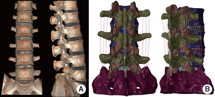
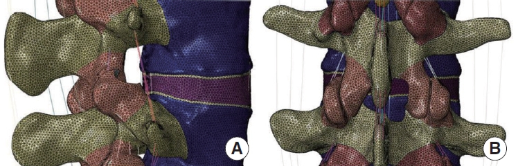
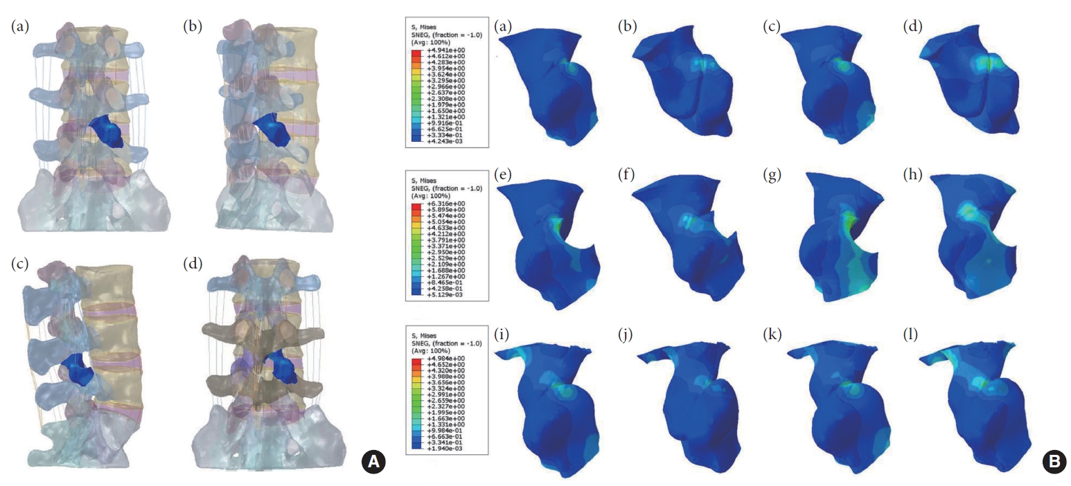
Based on the normal finite element model M0 (Fig. 1), the PTED surgical model M1 was simulated by using the finite element method to simulate the intraoperative use of a circular saw to resect a cylindrical region of 7.5 mm in diameter at the tip of the right synchondrosis of the L5 vertebra by making an angle of 30° with the coronal and horizontal planes [16]. Based on the M0 model, a computerized method was used to simulate the resection of the lower edge of the plate and the medial edge of the inferior articular eminence on the right side of the L4 vertebral body, as well as the upper edge of the plate on the right side of the L5 vertebral body, and the dissection of the intact ligamentum flavum, and to obtain the UBE surgical model M2 [13]. The surgical model is illustrated in Fig. 2.
5. Loading and Boundary Conditions
A compression load of 400 N and a torque of 7.5 Nm were applied to the upper surface of L3 to simulate 6 different movements of the spine: forward flexion and backward extension, left lateral bending and right lateral bending, left axial rotation, and right axial rotation. The inferior end of the sacrum was utterly immobilized. A slight sliding friction was used between the articular cartilages, and surface penetration was strictly controlled by setting the tangential and normal friction behavior to a small friction coefficient of 0.1 [27].
6. Ethics Statement
All experimental protocols were approved by the Independent Ethics Committee of Bengbu Medical College (2023YJS181), and the subjects gave informed consent to this work. Written informed consent was obtained from the individual(s) for the publication of any potentially identifiable images or data included in this article.
RESULTS
1. Mesh Generation Results
To ensure that the accuracy of the calculation meets the requirements of finite element analysis, we control the mesh type and mesh size, in which the base alignment model has a total of 993886 cells, of which 126768 are shell cells, and 81 are truss unit cells.
2. Indirect Validation Results
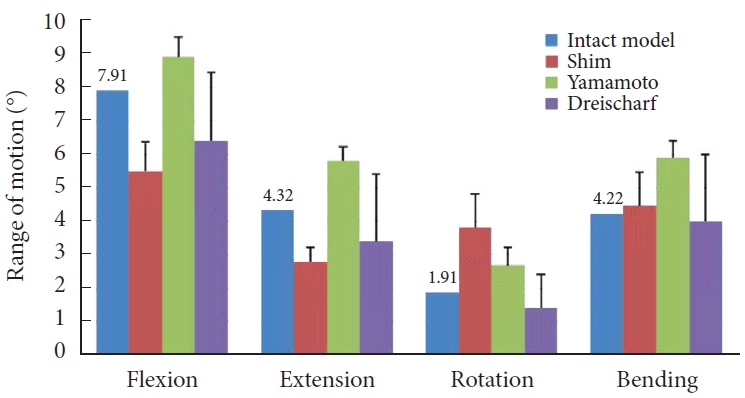
A concentrated force of 400 N and a moment of 7.5 Nm were applied to the normal lumbar spine finite element model M0. Its ROM values were measured and recorded under 4 motion states: bending, extension, lateral bending, and axial rotation, and the experimental results were compared with the experimental data in the previous literature [28-30]. The results show (Fig. 3) that the ROM values of model M0 are within the range of other scholars’ research data, proving that the model M0 established in this study is valid.
3. Range of Motion
1) Normal model
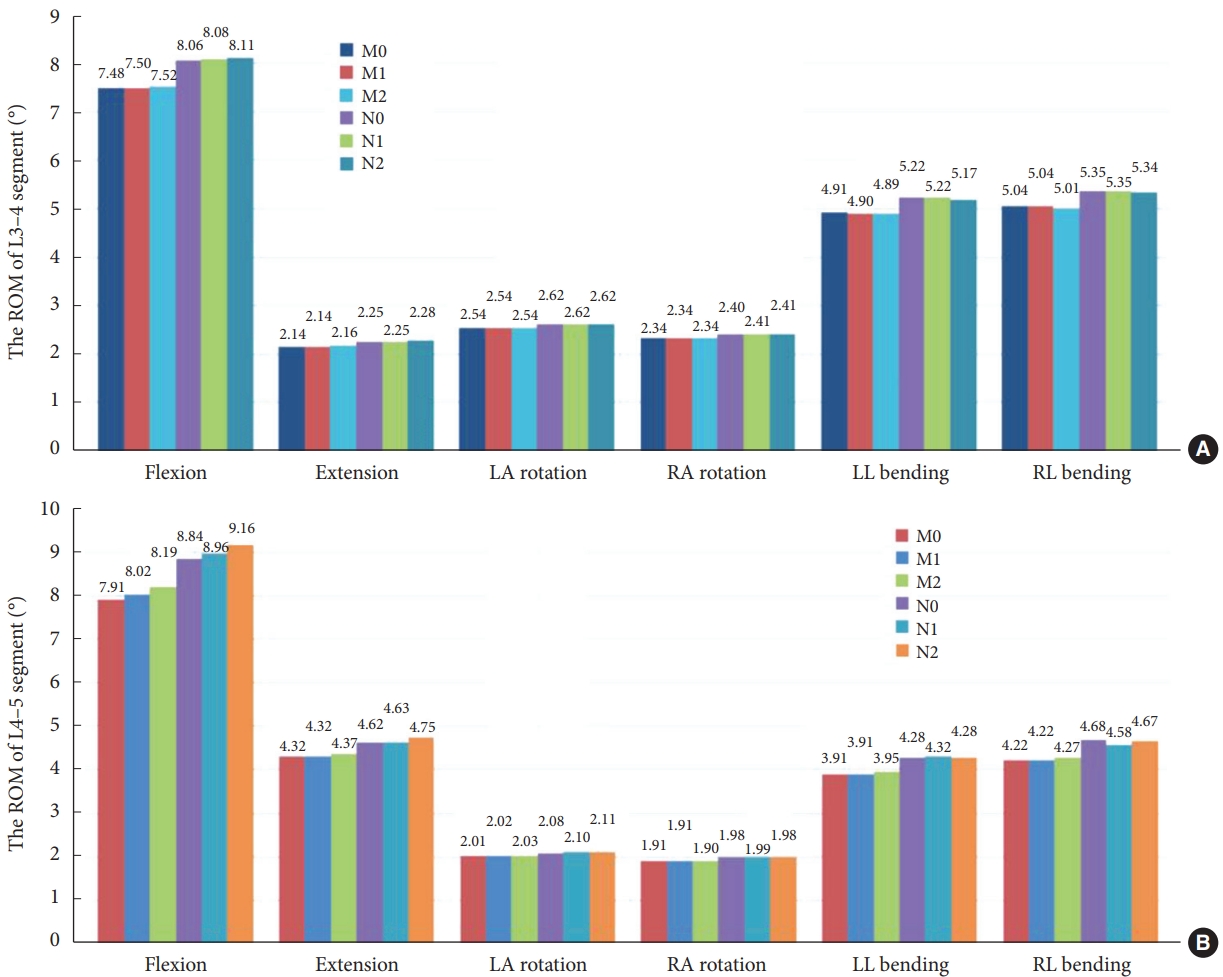
As shown in Fig. 4A, at the L3–4 segment, the ROM of models M1 and M2 did not change dramatically over the 6 operating conditions compared to model M0. As shown in Fig. 4B, at the L4–5 segment, there was no significant difference in ROM in 6 motion states for Model M1 compared to Model M0. Model M2 showed a 3.54% increase in ROM in forward flexion, and there was no significant change in ROM in the remaining motion states.
2) Osteoporosis model
At the L3–4 segment, there is no dramatic change in ROM for models N1 and N2 for the 6 motion states compared to model N0. At the L4–5 segment, compared with the osteoporotic lumbar spine model N0, model N1 showed no significant change in ROM during flexion, extension, left rotation, right rotation, and left lateral bending, and only a decrease of 2.14% in ROM during right lateral bending. Model N2 showed an increase of 3.62% and 2.81% in ROM during flexion and extension, respectively. There was no significant change in ROM in the remaining 4 motion states.
4. Maximum Displacement of Model
1) Normal model
As illustrated in Fig. 5, there is no substantial difference in the maximum displacement values of model M1 compared to model M0 for all conditions. The maximum displacement values of model M2 increased in all 6 working conditions, with an increase of 2.05% in forward flexion and the most significant increases of 16.88% and 17.82% in left and right lateral bending.
2) Osteoporosis model
Compared to model N0, N1 showed a slight increase in maximum displacement values in flexion, extension, left-right rotation, and left lateral bending, where the maximum displacement value increased by 4.48% in left lateral bending but decreased by 20.28% in right lateral bending. The maximum displacement values of N2 increased by 2.23%, 21.94%, and 3.23% in flexion and left-right lateral bending, individually, and there was no significant difference in the maximum displacement values for the remaining work conditions.
5. Maximum von Mises Stress of the Intervertebral Disc
1) Normal model
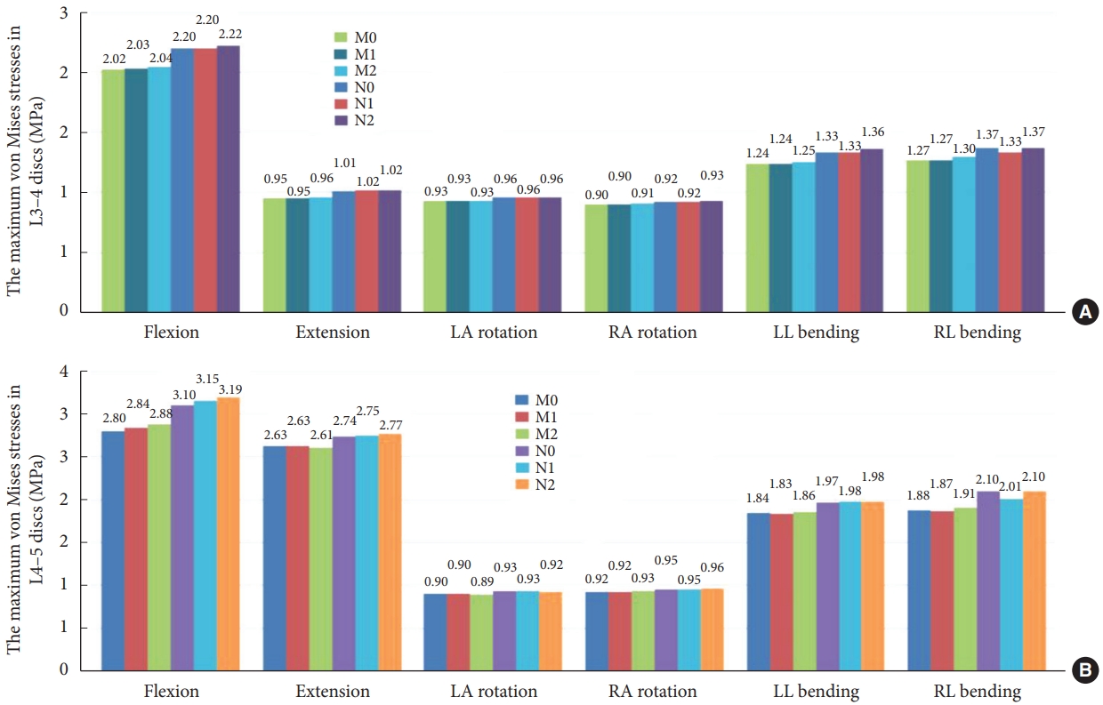
At the L3–4 segment (Fig. 6A), there was no meaningful change in maximum disc stress between models M1 and M2 at the 6 working conditions compared to model M0. Fig. 6B shows that at the L4–5 segment, there was no significant change in maximum disc stress in the 6 motion states for model M1 compared to model M0. Model M2 showed a 2.64% increase in maximum disc stress during forward flexion, and there was no significant change in maximum disc stress during the remaining 5 motion states.
2) Osteoporosis model
At the L3–4 segment, compared to model N0, model N1 showed a 3.20% decrease in maximum disc stress only during right lateral bending, and model N2 showed no significant change during the 6 motion states. In the L4–5 segment, compared to model N0, model N1 showed a 4.34% decrease in maximum disc stress during right lateral bending, model N2 showed a 2.84% increase during forward flexion, and there was no notable variation in maximum disc stress for the remaining motion states.
6. L4–5 Maximum Stress and Stress Distribution
1) Normal model
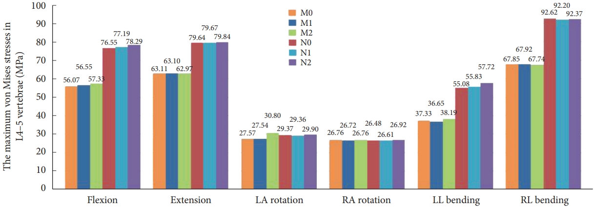
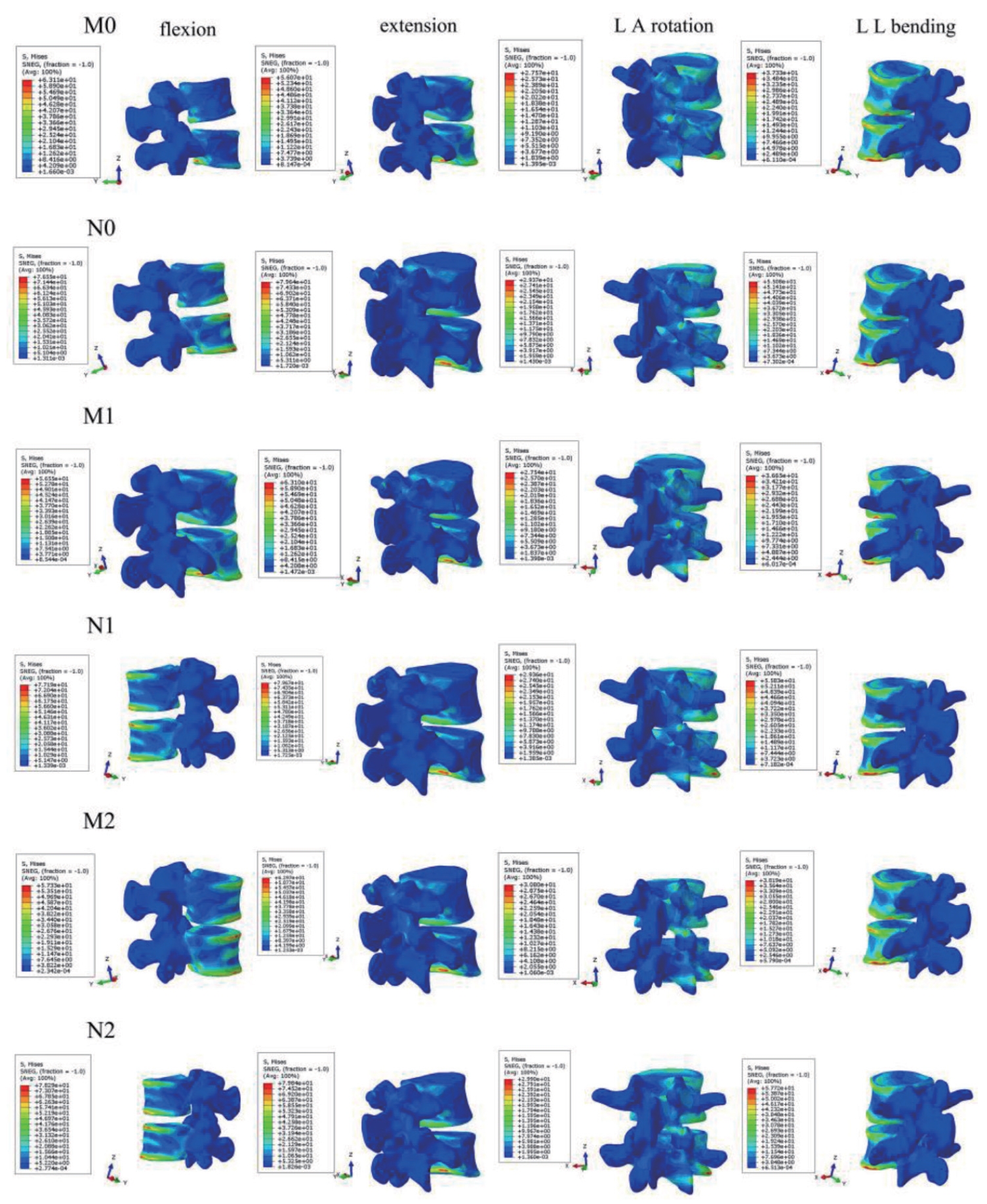
Fig. 7 demonstrates that the maximal stress values of M1 in the six-movement states do not differ considerably from model M0. Model M2 showed a slight increase in maximum stress values during flexion, left rotation, and left lateral bending, with a marked increase of 11.72% during left rotation and no apparent change during the remaining movements. Fig. 8 illustrates that models M0, M1, and M2 stresses are distributed at the anterior and posterior edges of the vertebral body in the flexion and extension conditions. Stress distribution was focused on the left and right sides of the vertebral body during right and left lateral bending. In the right rotation, there was no apparent tendency for the stress distribution to focus. In left rotation, the stress distribution of models M0 and M1 was focused at the right edge of the vertebral body and the tip of the right articular eminence, and the stress distribution of model M2 was located at the right edge of the vertebral body, the tip of the right articular eminence, and the right lower edge of the L4 vertebral plate.
2) Osteoporosis model
The stress distribution in the osteoporosis group followed the same trend as in the normal bone group. Compared to the N0 model, there was no meaningful change in the maximum stress value of N1 for the 6 conditions. N2 significantly increased the maximum stress value in forward flexion and left lateral bending, which increased by 2.27% and 4.79%, respectively. There is no substantial difference in the maximum stress values for the remaining conditions.
7. L4–5 Right Articular Process Stress and Stress Distribution
1) Normal model
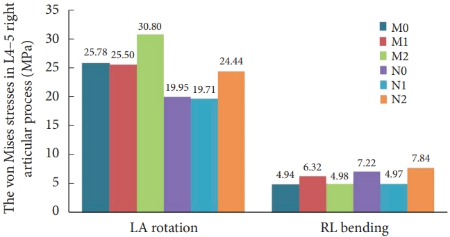
There was no contact or stress generation on the articular surface of the right articular process of the L4–5 surgical segment during flexion, extension, right rotation, and right bending to the right. Fig. 9 illustrates that in the left rotation and right lateral bending states, the stresses of models M0 and M2 were concentrated in the apical part of the right articular eminence of L4–5, and the stresses of model M1 were distributed in the surgically shaped region of the right articular eminence. Fig. 10 displays no meaningful variation in the right articular eminence stress at L4–5 for model M1 and an increase of 19.47% for model M2 in the left rotation state compared to model M0. In right lateral bending, there was a 27.83% increase in right articular process stress in model M1 and a slight increase in right articular process stress in model M2.
2) Osteoporosis model
The trend of stress distribution of the model in the osteoporotic group was consistent with that of the normal bone group, and the range of stress distribution was increased compared with that of the normal bone group. Compared with the osteoporotic model N0, in the left rotation state, the stress on the right articular process at L4–5 in model N2 increased by 22.51%. During right bending, the right articular process stress decreased by 31.09% in model N1 and increased by 8.69% in model N2.
3) Comparison of normal and osteoporotic model
Unlike normal model M1, model N1 showed a 22.71% and 21.28% decrease in right articular process stress during left rotation and right bending, respectively. Compared with model M2, model N2 showed a 20.65% decrease in right articular process stress during the left rotation and a 57.34% increase during the right bending. By verifying the experimental results, we believe that the above results may be related to the decrease in the load-bearing capacity of the vertebral body caused by the surgical shaping of the right side and osteoporosis. At the same time, the error of the sample experiments cannot be ignored.
DISCUSSION
Based on previous reports in the literature [31,32], spinal endoscopic surgery has gradually become one of the highly accepted treatment modalities for patients with LDH due to its superiority in terms of less soft tissue damage, faster postoperative recovery, significantly fewer postoperative complications, and relatively lower surgical costs compared to open spinal surgery. Currently, there are 2 types of mainstream spinal endoscopic surgery: PTED and UBE. Meanwhile, with an increasing aging society, the incidence of concomitant LDH in elderly patients with osteoporosis has increased dramatically [33]. Several scholars have conducted relevant studies using finite element methods for the biomechanical assessment of endoscopic spine surgery. For example, Li et al. [34] investigated the effects of percutaneous endoscopic supra-articular synchondroplasty in different positions on the biomechanical properties of the lumbar spine using a 3D finite element method. Li et al. [35] evaluated the effect on lumbar spine stability after using large annuloplasty and limited laminoplasty in TELD by finite element modeling.
In this experiment, we constructed six three-dimensional finite element models of the lumbar spine. First, we compared the mechanical differences between the normal bone model (M0) and the osteoporotic model (N0). Compared to the M0 model, the N0 model showed increased ROM, maximum displacement value, disc stress, and maximum stress value in all 6 motion states, indicating that osteoporosis leads to decreased spinal stability. By analyzing the ROM, we found that in the L3–4 segment, compared to models M0 and N0, models M1, M2, N1, and N2 had no meaningful change in ROM in all movements, suggesting that the 2 surgical modalities, PTED and UBE, did not have a substantial effect on the ROM of the adjacent segments. At the L4–5 segment, compared with models N0, N1 had decreased ROM and maximum displacement values in right bending and increased maximum displacement values in left bending, which may be related to the destruction of the right synchondrosis during shaping and the decreased bony blockage of the right synchondrosis joints and the resistance of the joint capsule ligament to shear and torsion. Compared to models M0 and N0, models M2 and N2 had increased ROM and maximum displacement values in forward flexion and significantly increased maximum displacement values in left lateral bending and right lateral bending. Analysis of the displacement cloud suggested that this might be associated with the stripping of the posterior ligament flavum in the UBE shaping and that the loss of posterior ligamentous antagonism of the L4–5 segments during forward flexion and the destruction of the upper and lower vertebral plates during shaping exacerbated this effect. It is suggested that postoperative patients wear a lumbar apron to protect them from excessive lumbar flexion, extension, and lateral bending activities. In addition, we found that using the same surgical approach, the ROM and maximum displacement values for all movements were increased in the osteoporotic model compared to the normal model. The reasons for this were analyzed as follows: the strength of the bony structures was significantly reduced in osteoporotic patients, while the ROM limitation of the osteoporotic model was not as good as that of the normal model.
Further analyzing the maximum von Mises stress, the L4–5 maximum stress value, and the associated stress cloud of the intervertebral disc. We found that the stresses of the 6 models were distributed at the anterior and posterior margins of the disc during flexion and extension. During rotation motion, the stresses of the models were distributed at the anterior and lateral margins of the disc. In the bending condition, the stresses are distributed on both sides of the disk. Compared with model N0, model N1 showed a decrease in disc stress during right lateral bending at the L3–4 and L4–5 segments, which may be related to the apical molding of the right synchondrosis and the loss of bony support and antishear stress on the right side in the right lateral bending condition, as shown in the study by relevant scholars [34,36], which was aggravated by osteoporosis. In the L4–5 segment, models M2 and N2 showed an increase in intervertebral disc stress during forward flexion compared to models M0 and N0, and in combination with the stress cloud diagrams, we believe that this may be related to lamellar shaping as well as ligamentum flavum stripping and that the abnormal stress distribution may lead to stress concentration and ultimately cause damage to the disc structure, resulting in an increased risk of disc degeneration, which is consistent with the research findings of Du et al. [37]. On the other hand, compared to models M0 and N0, models M2 and N2 showed an increase in maximum stress during flexion and a slight increase in maximum stress and L4–5 synchondrosis stress during left rotation, which may be related to the fact that the lamina transfers the load through the spine and restricts the movement of the vertebrae, and laminoplasty causes impairment of this function. Furthermore, for the same surgical procedure, the osteoporotic model showed an overall increase in disc stress and maximum stress values compared to the normal bone model. Considering the decreased density of cortical and cancellous bone in osteoporotic patients affects the stiffness and strain values of the bone, which alters the vertebral body’s intradiscal pressure and loading pattern. The results of the stress cloud maps showed that in the left-rotated state, the stresses of models M1 and N1 were focused in the annular-shaped region of the tip of the right synchondrosis of L4–5. In contrast, the stresses of models M2 and N2 were distributed in the right lower margin of the L4 vertebral plate and the tip of the right synchondrosis of L4–5. In addition, the stress distribution area of the osteoporotic model was increased relative to that of the normal model, indicating that osteoporosis may have increased the stress distribution area of the vertebral body.
The findings of the current analysis demonstrated that the ROM, maximum displacement values and disc stresses in the PTED surgical model with osteoporosis decreased during right lateral bending and increased during left lateral bending. The stress cloud maps indicated that the strains were distributed in the annularly shaped region of the right synchondrosis tip during left lateral bending. Related studies have demonstrated [34,38] that the articular process and the intervertebral disc form a triple-jointed complex that jointly maintains spinal stability, and the cylindrical structure of the intervertebral disc facilitates lumbar rotational motion. At the same time, the cartilaginous surface of the articular process is perpendicular to the horizontal plane, and the sagittal plane at about 45° to the stacked tile-like structure, which limits the vertebral body’s lateral bending and rotational motion. In this experiment, the surgical simulation of L5 right supraspinous apophyseal molding destroyed the articular eminence and the capsular ligament. The bony block of the articular eminence and the limiting effect of the capsular ligament against shear and torsion in rotation and lateral bending are lost so that the ROM, the value of the maximum displacement, and the intervertebral disc stresses change accordingly, which is aggravated by osteoporosis. The UBE model showed increased ROM, maximum displacement value, and intervertebral disc stress in flexion. The maximum stress and displacement values increased in lateral bending movement. The maximum stress value and the articular synaptic stress increased slightly during the left rotation, and the stress was distributed over the lower edge of the right lamina of L4 and the tip of the L4–5 articular process. It has been suggested [39] that the articular synaptic joints are separated when the lumbar spine is forward flexion. The joint capsule is strained, with the posterior ligaments counteracting their loads. At the same time, the spine transfers load through the vertebral plates, limiting vertebral motion, especially in extension and rotation conditions. The shaping of the plate and stripping of the ligamentum flavum at the L4–5 segment in this experiment may have contributed to the impairment of these functions. In conclusion, in the normal spine and osteoporotic spine, there was no apparent difference in ROM and disc stress at L3–4 and L4–5 levels under all working conditions between the 2 surgical models. The distribution area of the L4–5 vertebral stress cloud map was the same as that of the intact model, indicating that the 2 surgical methods were less destructive to the physiological structure of the spine. Furthermore, in contrast to the normal model, ROM, maximal displacement, maximal stress, and disc stress were increased in the osteoporotic model in all motion states regardless of the surgical approach, which was also confirmed by the results of the stress cloud diagrams. Through analysis of relevant research, we considered that the reasons might be twofold. Firstly, the ROM limitation of the normal model was more substantial than that of the osteoporotic model. Secondly, the elastic modulus of the normal model was better than that of the osteoporotic model. The decrease in the density of cortical and cancellous bone affected the stiffness and strain values of the bone, which decreased the ability of the vertebral body to withstand the pressure. The pressure on the intervertebral discs increased, which increased the risk of degeneration of the intervertebral discs [40]. Therefore, we concluded that the biomechanical stability of the normal model was more substantial than that of the osteoporotic model when the surgical approach was the same, i.e., the safety of the normal patient is superior to that of the osteoporotic patient.
By comparing the previous literature, this study is the first to use the computerized finite element method to evaluate the effects of 2 surgical procedures, PTED and UBE, and osteoporosis, on the mechanical properties of the spine. At the same time, this experiment has some limitations. First, the spinal model of L3–S1 was constructed on the assumption of healthy adults without spinal diseases, without considering the effects of related diseases on the spinal structure, and the construction of paravertebral soft tissues was not detailed enough. Secondly, establish an osteoporosis model by lowering the elastic modulus of normal model cortical and cancellous bone, and the individual variability needed to be sufficiently considered. Finally, this analysis was conducted experimentally using computer simulations and lacked relevant cadaveric studies. Whether the above factors may have affected the experiment results needs to be further verified by a series of in vitro biomechanical and clinical studies.
CONCLUSION
In this research, the effects of 2 surgical approaches, PTED and UBE, and osteoporosis on the biomechanical properties of the lumbar spine were comparatively from a biomechanical point of view, based on the computerized finite element method. The experimental results demonstrated that the 2 surgical methods were less destructive to the physiological structure of the spine in both normal and osteoporotic spines. In addition, using the same endoscopic spine surgery, normal spine biomechanical properties are superior to osteoporotic spines.