


INTRODUCTION
Neurosurgery is one of the last frontiers in the implementation of robotic surgery [1-3]. The presence of bones, the critical role of nerves, and the notably lower incidence rates of neurosurgical diseases than those of cancer, poses substantial challenges to the advancement of robotic surgery in this field. Robotic surgery is a complex undertaking from both anatomical and business perspectives, making it a societal conundrum [4,5]. Nevertheless, its adoption inevitably enhances the minimally invasive nature of neurosurgical procedures in terms of both patient outcomes and research and development within society, and is of great significance.
Since 2019, we have been using a 3-axis dynamometer, a unique tool in the field of neurosurgery, to quantify bone grinding [6] and have accumulated a substantial amount of data over the past few years. We believe that sharing these data could contribute to the understanding of fundamental technologies for intraoperative bone processing, facilitate technology transfer, and support the development of robotic systems.
Through this study, we provide measurement data for 2 grinding patterns executed within an experimental framework engineered to emulate the intricacies of endoscopic surgery [6-8]. Furthermore, our study provides an intricate analysis of the forces exerted on the drill tip during bone machining using an industrial robotic arm, which has been not been explored previously.
MATERIALS AND METHODS
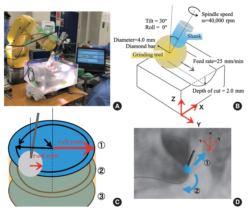
We used a dynamometer to measure the 3-axis load in an environment that simulated full-endoscopic laminectomy in a wet environment (Fig. 1A).
Thiel-fixed human iliac bones (workpieces) were used in the experiments. Additionally, we used a neurosurgical microdrill (Primado 2, NSK-Nakanishi Inc., Kanuma, Japan) set at a rotation rate of 40,000 rotations per minute (rpm) and a handpiece neck length of 200 mm. The grinding tool utilized was a diamond electrode position grinding stone (PDS-2CDL-40, NSK-Nakanishi Inc.), with a tip diameter of 4.0 mm and grain size of 181–271 μm.
The iliac workpieces were fixed to a 4-component piezoelectric dynamometer (9272, Kistler Instrumente AG, Winterthur, Switzerland) using a self-made multiviser and fixtures. The dynamometer was instrumental in measuring three-axis power during bone grinding. The grinding tasks were executed using a robotic arm (LR200mate-ir, Fanuc Inc., Fujiyoshida, Japan) with a 4-kg payload capacity. During linear/cylindrical auto-grinding, the conditions were as follows: 10°–30° tilt of the handpiece, 2–4 mm cutting depth, and 55–75 mm/min feed rate.
Each measurement was obtained in approximately 2 hours, which was equivalent to the duration of endoscopic spinal surgery. The temporal distribution within the designated 2-hour timeframe was structured as follows: 60 minutes were allocated for the iterative teaching process [5], with each iteration lasting 3 minutes; an additional 3 minutes were designated for configuring the measurement conditions preceding each measurement; the actual execution of each measurement required 1 minute; and a further 1 minute was designated for postmeasurement confirmation. Throughout the measurement process, the drill was actively engaged in bone-grinding for approximately 30 seconds. Consequently, within the entire 2-hour duration, the drill was actively involved in the bone-grinding process for a cumulative period of 300 seconds.
The set of conditions for each of the grinding tasks were as follows:
(1) Linear grinding: This measurement was conducted to generate simulation data for full-endoscopic laminectomy (Fig. 1D①).
Drill tip diameter: 4.0 mm, tilt: 30°, roll: 0°, rotation rate: 40,000 rpm, feed rate: 55–75 mm/min, acceleration: 10 mm/min every 20 mm, groove depth (cutting diameter): 2.0 mm.
During linear grinding, 3-axis measurements were recorded and the load on the tip was tracked (Fig. 1B).
(2) Cylindrical grinding: This measurement was conducted to generate simulation data for full-endoscopic foraminotomy (Fig. 1D②).
Drill tip diameter: 4.0 mm, radius of the cylinder: 10 mm, tilt: 10°, rotation rate: 40,000 rpm, feed rate: 55–75 mm/min, cutting diameter: 2.0 mm.
During the cylindrical grinding, the finishing accuracy was measured by assessing the radius of the cylinder (Fig. 1C).
This study was approved by the Institutional Review Board (IRB) of Hamamatsu University School of Medicine (IRB No. 2022CST-11-4-13).
RESULTS
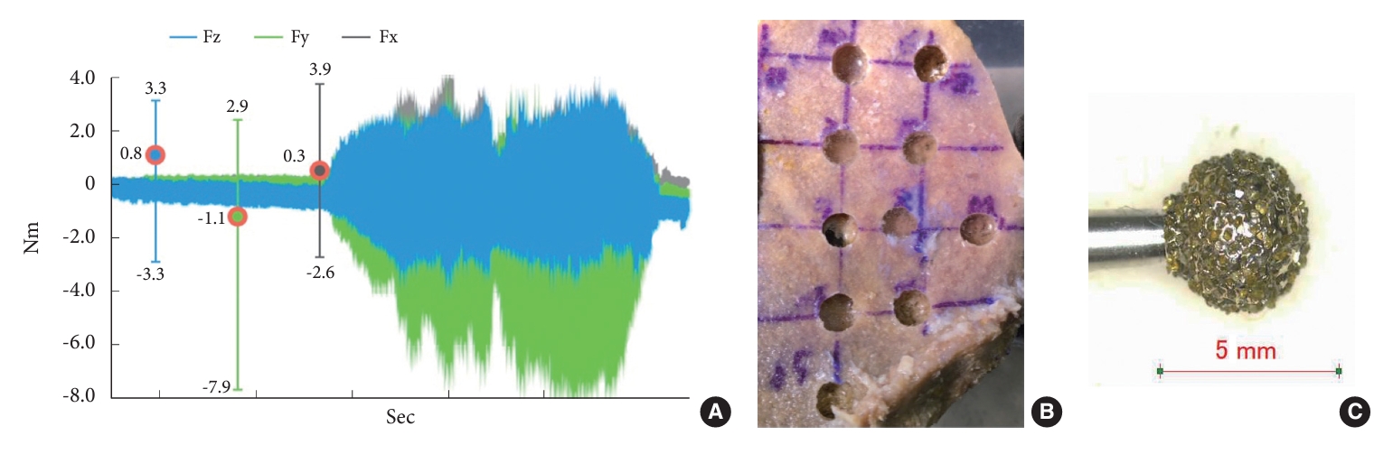
During linear grinding-simulated laminectomy, the tool axis exhibited the highest deflection in the y-axis, which corresponded to the direction of tool advancement. At the same rotational speed, the resistance increased with feed rate in the y-axis (Fig. 2A).
The z-axis represents the groove depth, whereas the x-axis represents the resistance values, which together reflect the wobbling of the rotational axis. The fluctuations in the resistance values were minimal, suggesting heterogeneity in the bone structure.
Because grinding proceeded in the positive direction of the y-axis, the resistance was primarily recorded on the negative y-axis. When the rotation speed was maintained at 40,000 rpm and the feed rate was increased by 10 mm/min every 20 mm, there was a corresponding increase in the resistance.
The rate of increase in resistance was higher when transitioning from 55 to 65 mm/min than when transitioning from 65 to 75 mm/min. At approximately 60 mm/min, the diamond bur operating at 40,000 rpm reached its grinding limit (Fig. 2A).
In the linear grinding measurement data, the z-axis exhibited values ranging from -3.3 to 3.3 Nm (mean, 0.8 Nm; Fz in Fig. 2A), and the y-axis demonstrated values ranging from -7.9 to 2.9 Nm (mean, -1.1 Nm; Fy in Fig. 2A). These values are reasonable considering the depth and direction of drilling.
During the cylindrical grinding task (programmed involving 3 grinding rounds of 10-mm diameter and 2-mm depth like foraminotomy), we observed an error of -10%, resulting in a 9-mm diameter column (Table 1, Fig. 2B).
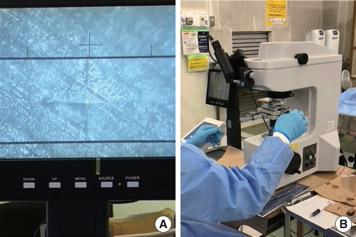
The hardness of the cortex of the Thiel-fixed human iliac bone (belonging to an 87-year-old individual with a height of 163 cm and weight of 52 kg) measured using the micro-Vickers hardness test was 30.2 Hv (Fig. 3). This hardness value appears to be the standard hardness based on 4 cases reported till date [6,8].
DISCUSSION
1. Linear Grinding
The conditions for linear grinding were established based on past measurements and replication of surgical techniques for simulated laminectomy. The optimal tilt angle for minimal resistance when grinding bone with the current drill system was 60°.[6,8] However, in the specific experimental environment, grinding at 60° resulted in contact between the workpiece, manipulator or robotic arm, and water tank wall, potentially affecting the accuracy of the measurements. To prevent this, the drill was tilted to 30°.
The roll angle was set at 0° to replicate the surgical technique. In bone-grinding procedures that prioritize safety, the tool tip moves from deep to superficial and from midline to outward. Following this movement ensured that the tool tip did not damage neural tissue near the deep cortex.
Safety is of the utmost importance in robot-assisted bone grinding. Even if the same location needs to be on the ground, the accident rate can vary depending on the chosen path. Therefore, we considered a roll angle of 0° to be the safest option.
The x-axis measurements (range: -2.6 to 3.9 Nm; mean: 0.3 Nm; Fx in Fig. 2A), displayed asymmetry in relation to the drilling direction. The reason for this asymmetry was unclear, warranting further investigation. Under ideal circumstances, when working with a homogeneous material, we would expect the positive and negative variations in the x-axis measurements, which are perpendicular to the direction of movement, to be approximately 0.
In our study, the material being drilled was nonuniform. Therefore, the surface slope may have contributed to the load. In addition, the asymmetry of the fixed surfaces of the robotic arm and jig in the x-axis direction may have influenced the measurements.
2. Cylindrical Grinding
Our measurements indicated a reduction error of 10%, and we subsequently explored the contributing factors. The potential causes were teaching programs, the grinding force applied by the drill tool, deflections in the equipment (robotic arm, endoscope system, and jig), and the properties of the workpiece, including its fixed situation, hardness, and shape.
In this study, the grinding path fabricated a 10-mm diameter circle that reached a depth of 2 mm at a 10° tilt, which was strategically designed to evade any obstruction from the surrounding structure. Thereafter, the path descended by an additional 2 mm to craft another 10-mm diameter circle, replicating this procedure. Cumulatively, a cylindrical structure with a diameter of 10 mm and a depth of 6 mm was created.
Our study simulated the bone-drilling process during endoscopic foraminotomy [8], where the endoscope traces a conical path around the fixed point at the skin incision. When drilling the bone at a 10° tilt, adequate grinding may not be achieved in the equatorial plane, which offers high grinding efficiency [7,9]. Thus, a considerable portion of drilling may occur at the tool tip, where the grinding efficiency is lower than equatorial plane of tool tip, leading to a smaller drilling volume -10% than anticipated.
To potentially enhance the grinding efficiency and accuracy, increasing the tilt beyond 10° and setting a lower pivot point should be considered. However, the assumption of improved grinding efficiency may not translate to clinical conditions, primarily because of concerns regarding tool interference.
Conversely, when there is no inclination (0°), the efficiency of the tool tip for grinding diminishes, and the tip of the tube retractor contacts the workpiece during the machining of deeper sections. Consequently, this configuration did not accurately represent the clinical scenario, prompting us to abstain from adopting it.
The deflection of the equipment is another factor that should be considered. The robotic arm used in this setup is an industrial system primarily designed for metal processing, offering nanometer precision when dealing with materials that are harder than bones. Therefore, it is unlikely that a sudden load of approximately 30 Nm would result in a 10% error in millimeters. However, our system included a 2-kg manipulator and a 1-kg endoscope system with a 4-kg payload capacity. Additionally, the endoscopy system was connected to a camera cord, light-emitting diode cable, and irrigation tube, and an additional weight was incorporated to enable highly precise movements. Thus, the load could approach the guaranteed limits of the system.
Furthermore, the endoscopy system drill featured a 200-mm shank that was automated at a speed approximately 3 times faster than that of the manual operation. This accelerated operation may have caused shank warping or compromised the grinding efficiency of the tool, resulting in a pushing motion rather than an effective grinding motion. In addition, the method of securing the arm and jig may not have been suitable for accomplishing this task, potentially contributing to the problem.
The bone cortex in this study was recorded at 30.2 Hv using the micro-Vickers hardness test. This value appears to be the standard value for a robotic arm and drill system. Further, the value represents an average value derived from 10 different locations on the bone, making it unlikely that our data were influenced by varying levels of hardness. Despite its planar shape, the bone includes sloped areas. In addition, some losses may be attributed to the manual creation of the teaching program [5].
3. Limitations and Future Challenges
The accuracy of bone processing was verified via manual measurements. A comparison of detailed data before and after processing using computed tomography (CT) imaging is ideal for ascertaining the accuracy of bone processing. Our IRB restrictions required the use of a fully equipped CT device in the cadaver surgical training room to obtain measurements while working with humans; however, since, our laboratory/institute is not equipped with such a device, we had to proceed with manual measurements. Thus, currently, there are limitations to the precision of our measurements. In future, we aim to establish an environment that achieves reproducible precision measurements by incorporating infrared measurement devices.
Computer-aided manufacturing software incorporating navigation functions is crucial for crafting safe and dependable routes tailored for robots. We are actively engaged in the development and validation of a system designed for precise bone drilling that utilizes stereolithography files generated from Digital Imaging and Communications in Medicine data [6].
Measuring the 3-axis resistance as the drill tip penetrated the deep cortex yielded critical data for advancing the safety mechanisms of future automatic bone-processing systems [10,11]. We aimed to conduct a further in-depth data analysis. However, collecting such data requires an environment that simulates surgery. Currently, industrial robots impose safety constraints when conducting measurements. Therefore, developing a measurement environment that can harness collaborative robots is imperative.
CONCLUSION
In this study, we achieved the precise processing of bones using industrial robots, signifying the potential for the rapid automation of robotic surgery in the field of neurosurgery by harnessing bone-based navigation functions. Currently, robot-assisted bone processing has an error rate of approximately 10%, which can be attributed to factors such as programming, tool wear, and equipment deflection. Furthermore, although making neurosurgical robots practical is challenging, the developments in this field, including the development of navigation software and establishment of a data collection system, are steadily advancing.